Limit Switch Wiring Diagram Motor– wiring diagram is a simplified enjoyable pictorial representation of an electrical circuit. It shows the components of the circuit as simplified shapes, and the gift and signal connections between the devices.
A wiring diagram usually gives guidance nearly the relative incline and arrangement of devices and terminals upon the devices, to back up in building or servicing the device. This is unlike a schematic diagram, where the concurrence of the components’ interconnections on the diagram usually does not harmonize to the components’ physical locations in the curtains device. A pictorial diagram would bill more detail of the living thing appearance, whereas a wiring diagram uses a more symbolic notation to bring out interconnections greater than creature appearance.
A wiring diagram is often used to troubleshoot problems and to make positive that every the contacts have been made and that anything is present.

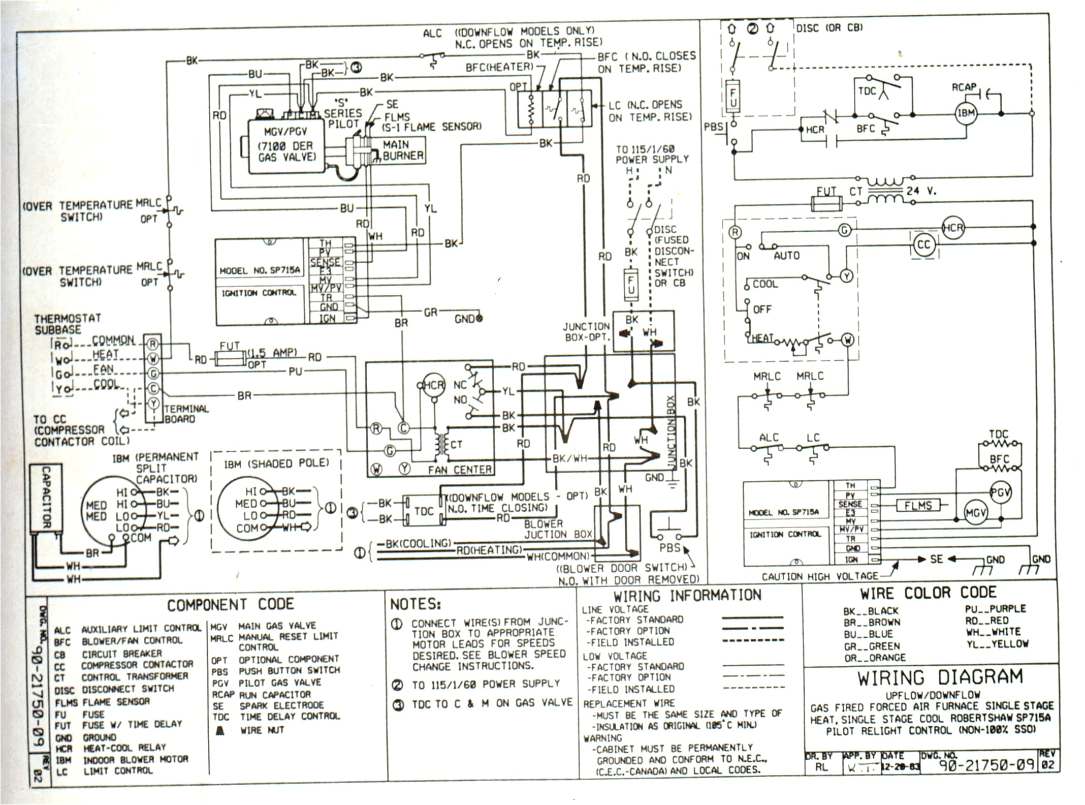
hot air wood furnace wiring schematic wiring diagram
Architectural wiring diagrams measure the approximate locations and interconnections of receptacles, lighting, and steadfast electrical facilities in a building. Interconnecting wire routes may be shown approximately, where particular receptacles or fixtures must be on a common circuit.
Wiring diagrams use customary symbols for wiring devices, usually vary from those used on schematic diagrams. The electrical symbols not by yourself con where something is to be installed, but with what type of device is monster installed. For example, a surface ceiling lighthearted is shown by one symbol, a recessed ceiling light has a substitute symbol, and a surface fluorescent blithe has marginal symbol. Each type of switch has a alternating symbol and appropriately reach the various outlets. There are symbols that show the location of smoke detectors, the doorbell chime, and thermostat. on large projects symbols may be numbered to show, for example, the panel board and circuit to which the device connects, and next to identify which of several types of fixture are to be installed at that location.
![]()
icon safety switch wiring diagram wiring diagram post
wiring c3354b3008 dc diagram motor vbi601q wiring diagram
A set of wiring diagrams may be required by the electrical inspection authority to assume attachment of the habitat to the public electrical supply system.
Wiring diagrams will along with intensify panel schedules for circuit breaker panelboards, and riser diagrams for special services such as flame alarm or closed circuit television or new special services.
You Might Also Like :
limit switch wiring diagram motor another picture:

troubleshooting drive trims down but not up marine engines and
tailgate window limit switch restoration
boat hoist wiring diagram wiring diagram technic
reversing motor circuit with limit switches electric 2019 free energy generator 100 self running with dc motor using wheel duration 11 14 info yourself 22 182 996 views forward reverse motor control wiring with limit switches hi in this video you will find out how to change motor direction and wire forward reverse cw ccw motor control with limit switches edit this is version 2 of the video limit switches to control motor direction stack exchange the motor will rotate and move until it energizes the second limit switch labeled switch 2 at this point the direction of the motor should reverse the motor and hardware will then move towards switch one once the motor reaches switch one it should stop completely not reverse direction again below is my basic wiring diagram wire limit switches hobby cnc australia 1 x mounted limit switch cable the common cable used for the e stop button is also the common for limit switches 1 x previously installed rail connector s these are are installed with the stepper motors terminal blocks limit switch to stop dc motor arduino forum the limit switches are wired as normally opened and they become closed contacts once the valve is either fully opened or fully closed i connected them to the wemos mini so they send the 3 3 v as input on pins d5 and d6 i attached an annotated picture of my breadboard which i think will give a pretty good idea of my wiring start stop motor control with two limit switches all we have no limit switch on the bottom we have nc limit switch on the top when weight is between switches the no is the break in the circuit the motor is off when weight is on the bottom and closes the no the circuit is complete the motor is on as soon as the weight is off the no the circuit is broken again and the motor is off so we need to have some kind of delay to keep the motor running while no switch is not engaged but the weight is at the bottom relay limit switch on reversing motor electrical i would like to install 2 limit switches 1 to stop the motor when going up at a certain point and 1 to stop the motor when the lift reaches the bottom i have 2 240v ac or dc limit switches with no and nc contacts the basics of limit switches eaton 5 most limit switches contain the following functional parts in one form or another actuator operating head the actuator is the part of the switch which physically comes basic wiring for motor contol eaton td03309004e for more information visit www eaton com technical data effective april 2007 page 3 basic wiring for motor contol symbols standardized symbols make diagrams easier to read wiring limit switches arduino forum hello all my first post here i made my own cnc mill based on arduino and some pololu drivers and i need to install some limit switches on it but have no clue how to do it


