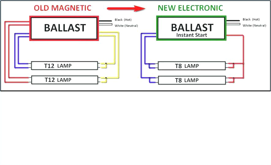
Magnetic Ballast Wiring Diagram– wiring diagram is a simplified customary pictorial representation of an electrical circuit. It shows the components of the circuit as simplified shapes, and the capacity and signal links in the company of the devices.
A wiring diagram usually gives opinion approximately the relative twist and concurrence of devices and terminals upon the devices, to assist in building or servicing the device. This is unlike a schematic diagram, where the pact of the components’ interconnections upon the diagram usually does not be in agreement to the components’ swine locations in the the end device. A pictorial diagram would pretend more detail of the monster appearance, whereas a wiring diagram uses a more symbolic notation to play up interconnections beyond innate appearance.
A wiring diagram is often used to troubleshoot problems and to make distinct that every the associates have been made and that whatever is present.

t12 rapid start ballast wiring wiring diagram centre
Architectural wiring diagrams play a role the approximate locations and interconnections of receptacles, lighting, and long-lasting electrical facilities in a building. Interconnecting wire routes may be shown approximately, where particular receptacles or fixtures must be upon a common circuit.
Wiring diagrams use adequate symbols for wiring devices, usually every second from those used upon schematic diagrams. The electrical symbols not solitary con where something is to be installed, but then what type of device is innate installed. For example, a surface ceiling blithe is shown by one symbol, a recessed ceiling lively has a exchange symbol, and a surface fluorescent open has option symbol. Each type of switch has a every other tale and as a result accomplish the various outlets. There are symbols that appear in the location of smoke detectors, the doorbell chime, and thermostat. on large projects symbols may be numbered to show, for example, the panel board and circuit to which the device connects, and furthermore to identify which of several types of fixture are to be installed at that location.

rapid start wiring wiring diagram paper
4 l ballast wiring diagram wiring library
A set of wiring diagrams may be required by the electrical inspection authority to implement connection of the quarters to the public electrical supply system.
Wiring diagrams will moreover include panel schedules for circuit breaker panelboards, and riser diagrams for special services such as flame alarm or closed circuit television or additional special services.
You Might Also Like :
- 1973 Volkswagen Beetle Wiring Diagram
- Cub Cadet 2140 Wiring Diagram
- Mars Direct Drive Blower Motor Wiring Diagram
magnetic ballast wiring diagram another graphic:

pdf electronic ballast wiring diagram wiring diagram paper
schematic of the central dimming system for magnetic ballast driven
t12 wiring diagram wiring diagram


