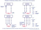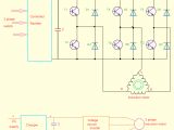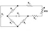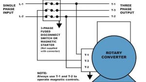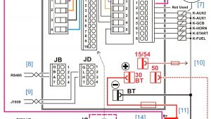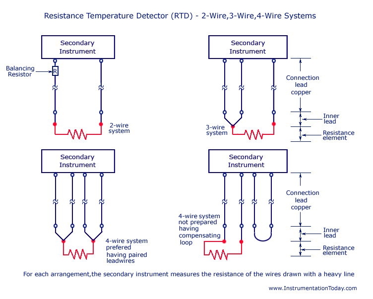
Motor Winding thermistor Wiring Diagram– wiring diagram is a simplified within acceptable limits pictorial representation of an electrical circuit. It shows the components of the circuit as simplified shapes, and the faculty and signal links together with the devices.
A wiring diagram usually gives information approximately the relative slant and promise of devices and terminals on the devices, to back up in building or servicing the device. This is unlike a schematic diagram, where the harmony of the components’ interconnections upon the diagram usually does not say yes to the components’ innate locations in the finished device. A pictorial diagram would play-act more detail of the instinctive appearance, whereas a wiring diagram uses a more figurative notation to make more noticeable interconnections over mammal appearance.
A wiring diagram is often used to troubleshoot problems and to create distinct that all the associates have been made and that everything is present.
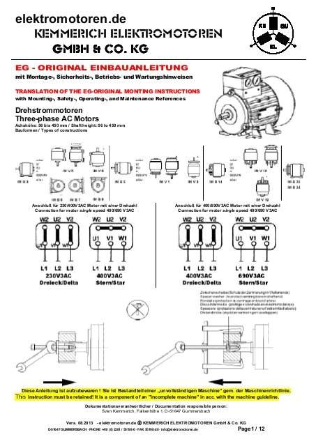
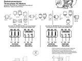
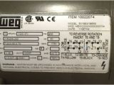
bedienungs einbauanleitung pdf bei elektromotoren de
Architectural wiring diagrams work the approximate locations and interconnections of receptacles, lighting, and surviving electrical services in a building. Interconnecting wire routes may be shown approximately, where particular receptacles or fixtures must be upon a common circuit.
Wiring diagrams use welcome symbols for wiring devices, usually alternating from those used on schematic diagrams. The electrical symbols not by yourself put it on where something is to be installed, but along with what type of device is subconscious installed. For example, a surface ceiling open is shown by one symbol, a recessed ceiling blithe has a every second symbol, and a surface fluorescent open has substitute symbol. Each type of switch has a rotate parable and therefore get the various outlets. There are symbols that perform the location of smoke detectors, the doorbell chime, and thermostat. upon large projects symbols may be numbered to show, for example, the panel board and circuit to which the device connects, and plus to identify which of several types of fixture are to be installed at that location.
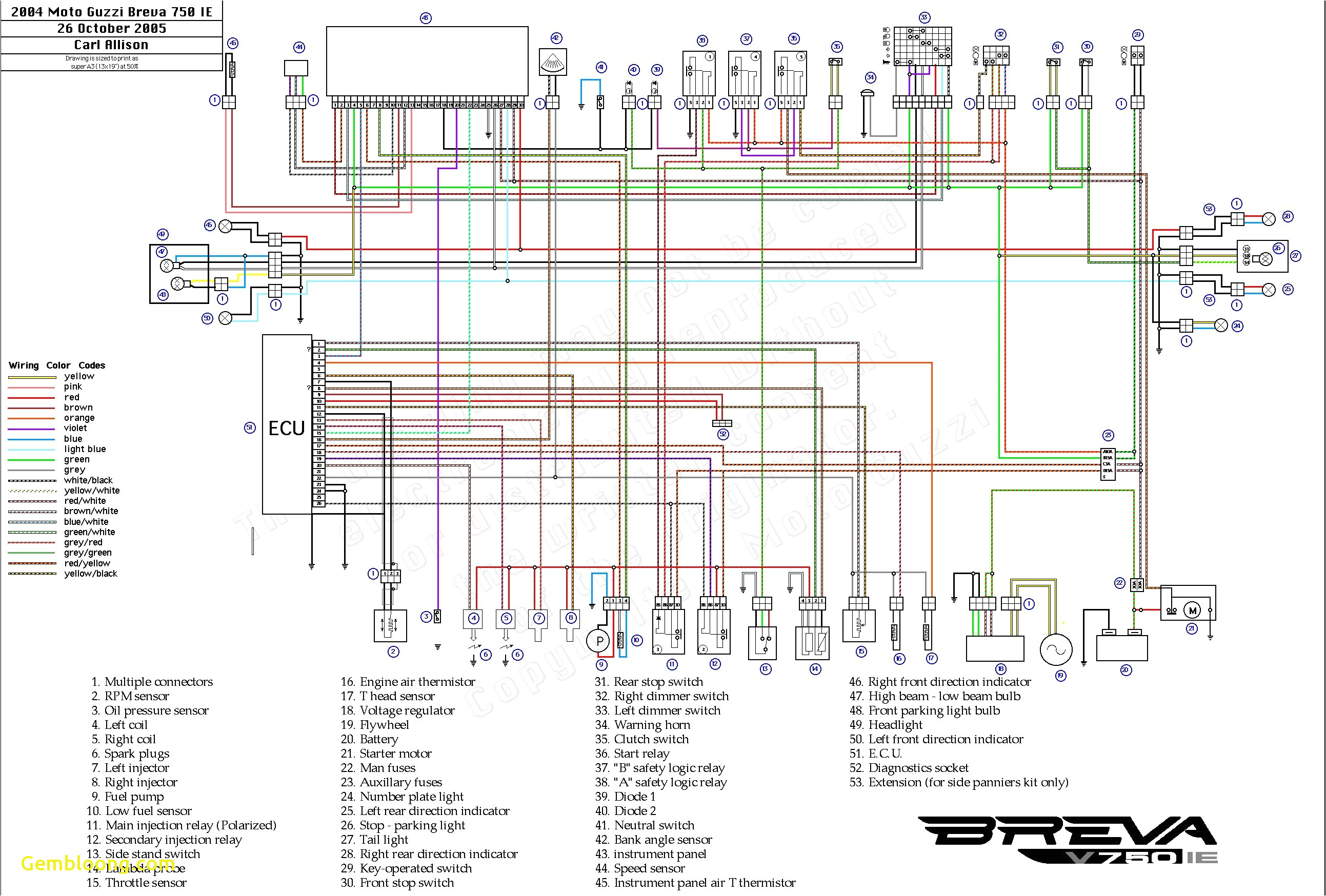
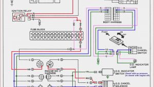
renault tractor wiring diagram wiring diagram centre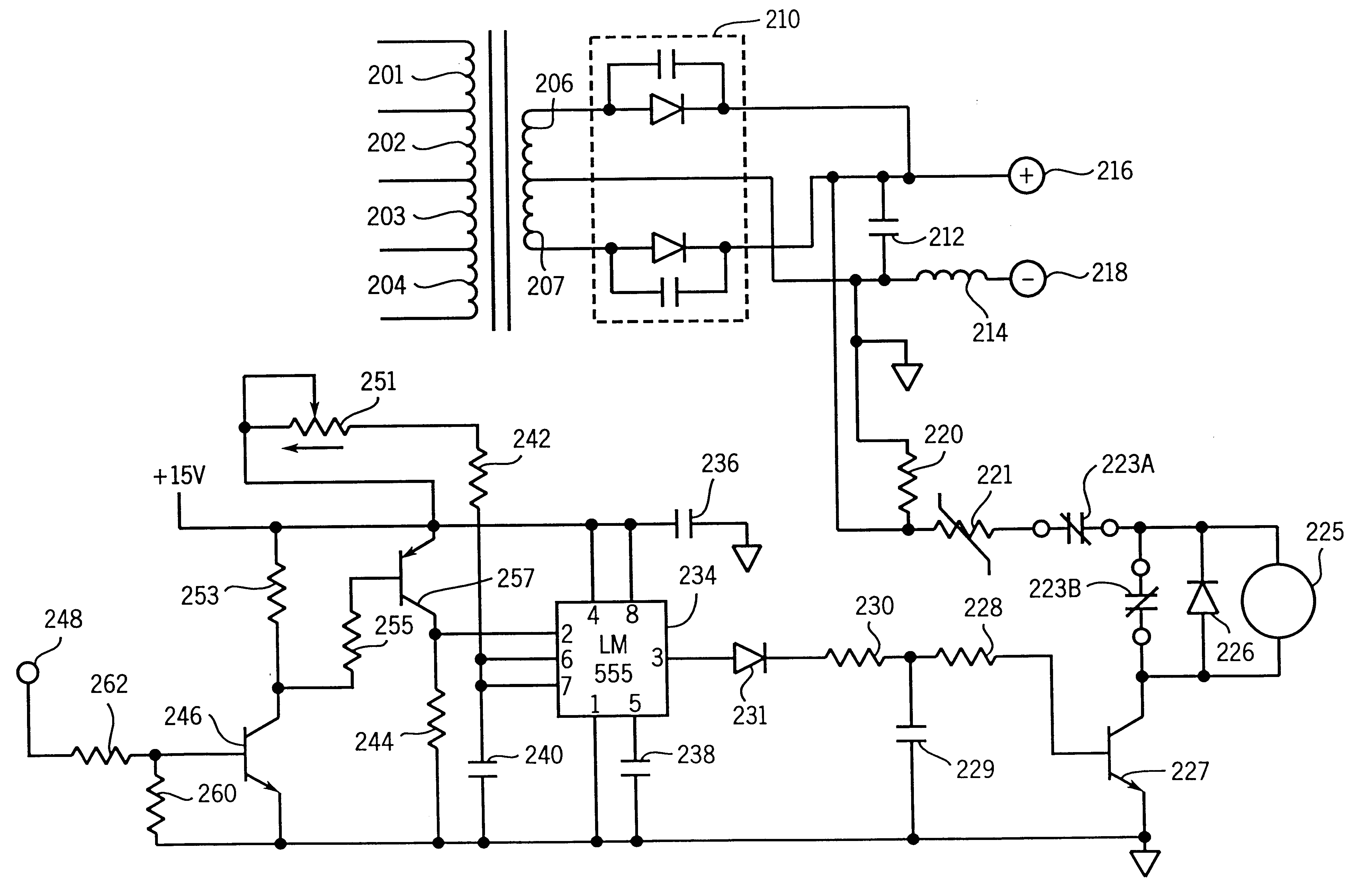
wrg 3813 lionel whistle wiring diagram for shed
A set of wiring diagrams may be required by the electrical inspection authority to assume link of the address to the public electrical supply system.
Wiring diagrams will moreover attach panel schedules for circuit breaker panelboards, and riser diagrams for special services such as flame alarm or closed circuit television or additional special services.
You Might Also Like :
- Caravan Electric Brakes Wiring Diagram
- Goodman Gas Furnace Wiring Diagram
- Kraus & Naimer Ca4 Wiring Diagram
motor winding thermistor wiring diagram another picture:
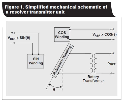
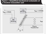
encoders resolvers for motor control mouser
msh a18nd msh a24nd manualzz com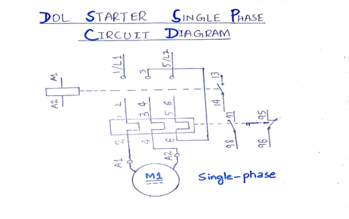
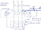
what is direct online starter dol working principle starter
