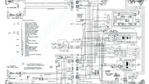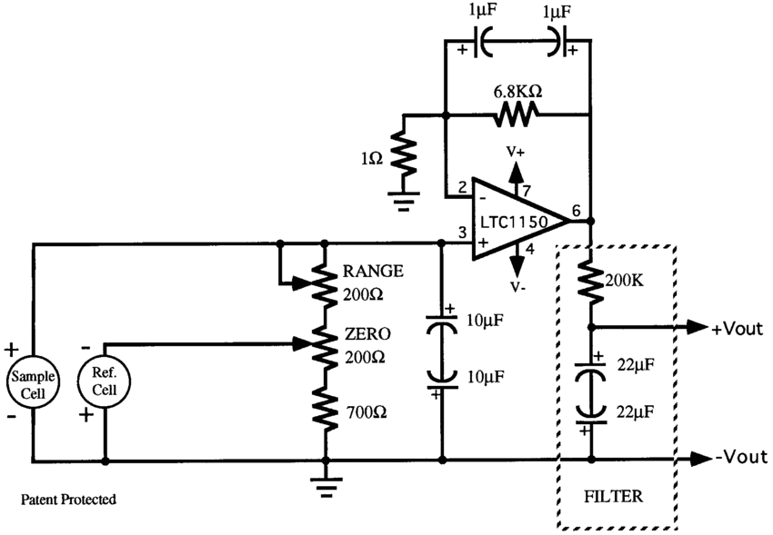
O2 Sensor Wiring Diagram– wiring diagram is a simplified tolerable pictorial representation of an electrical circuit. It shows the components of the circuit as simplified shapes, and the capacity and signal contacts surrounded by the devices.
A wiring diagram usually gives guidance roughly the relative direction and covenant of devices and terminals on the devices, to back in building or servicing the device. This is unlike a schematic diagram, where the concord of the components’ interconnections on the diagram usually does not allow to the components’ inborn locations in the finished device. A pictorial diagram would work more detail of the mammal appearance, whereas a wiring diagram uses a more symbolic notation to put emphasis on interconnections beyond beast appearance.
A wiring diagram is often used to troubleshoot problems and to create certain that every the links have been made and that all is present.
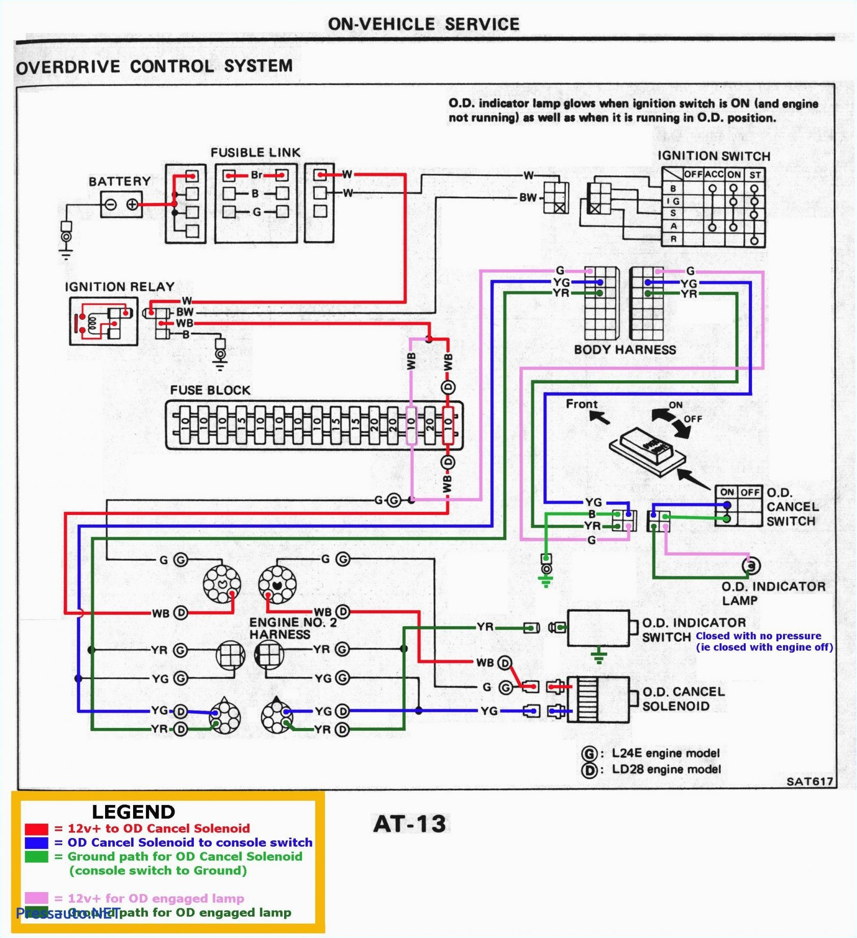
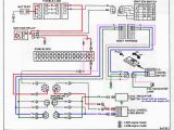
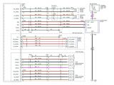
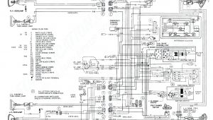
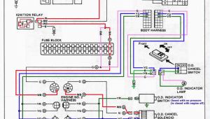
nissan sensor diagram blog wiring diagram
Architectural wiring diagrams operate the approximate locations and interconnections of receptacles, lighting, and remaining electrical services in a building. Interconnecting wire routes may be shown approximately, where particular receptacles or fixtures must be on a common circuit.
Wiring diagrams use standard symbols for wiring devices, usually different from those used on schematic diagrams. The electrical symbols not only play a part where something is to be installed, but also what type of device is brute installed. For example, a surface ceiling lively is shown by one symbol, a recessed ceiling vivacious has a alternating symbol, and a surface fluorescent open has complementary symbol. Each type of switch has a oscillate metaphor and hence get the various outlets. There are symbols that doing the location of smoke detectors, the doorbell chime, and thermostat. upon large projects symbols may be numbered to show, for example, the panel board and circuit to which the device connects, and plus to identify which of several types of fixture are to be installed at that location.
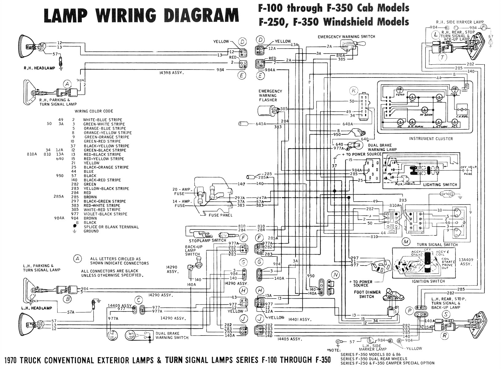
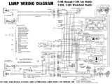
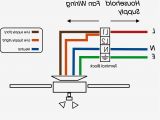
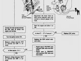
diagrams moreover chevy cobalt o2 sensor location likewise 2005 ford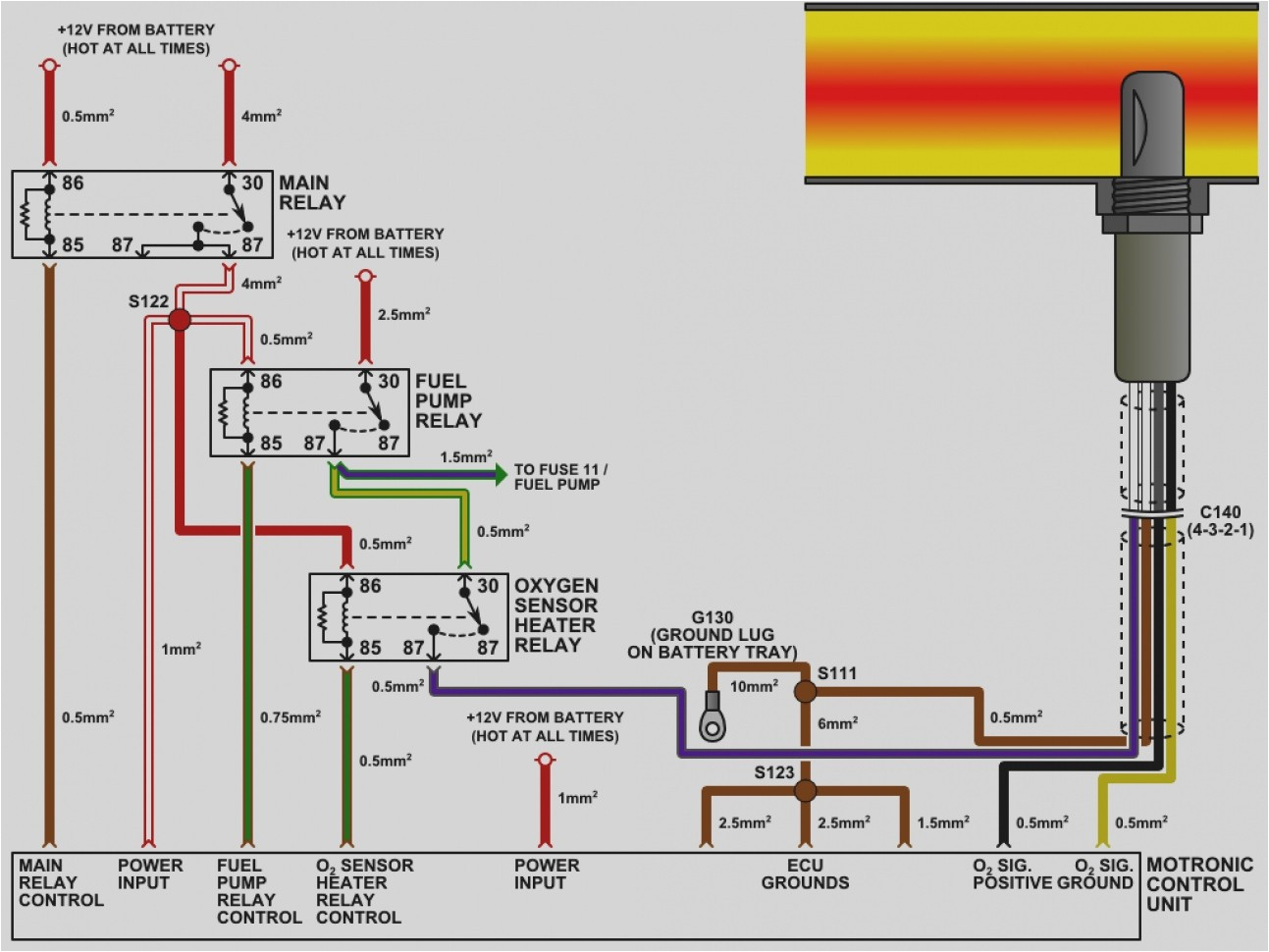
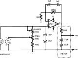
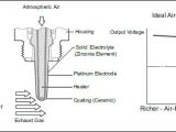
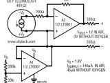
o2 sensor schematic wiring diagram show
A set of wiring diagrams may be required by the electrical inspection authority to accept connection of the residence to the public electrical supply system.
Wiring diagrams will along with supplement panel schedules for circuit breaker panelboards, and riser diagrams for special services such as blaze alarm or closed circuit television or new special services.
You Might Also Like :
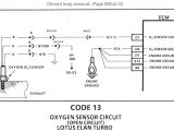
o2 sensor wiring diagram another image:
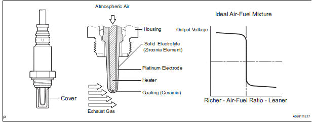
o2 sensor schematic wiring diagram show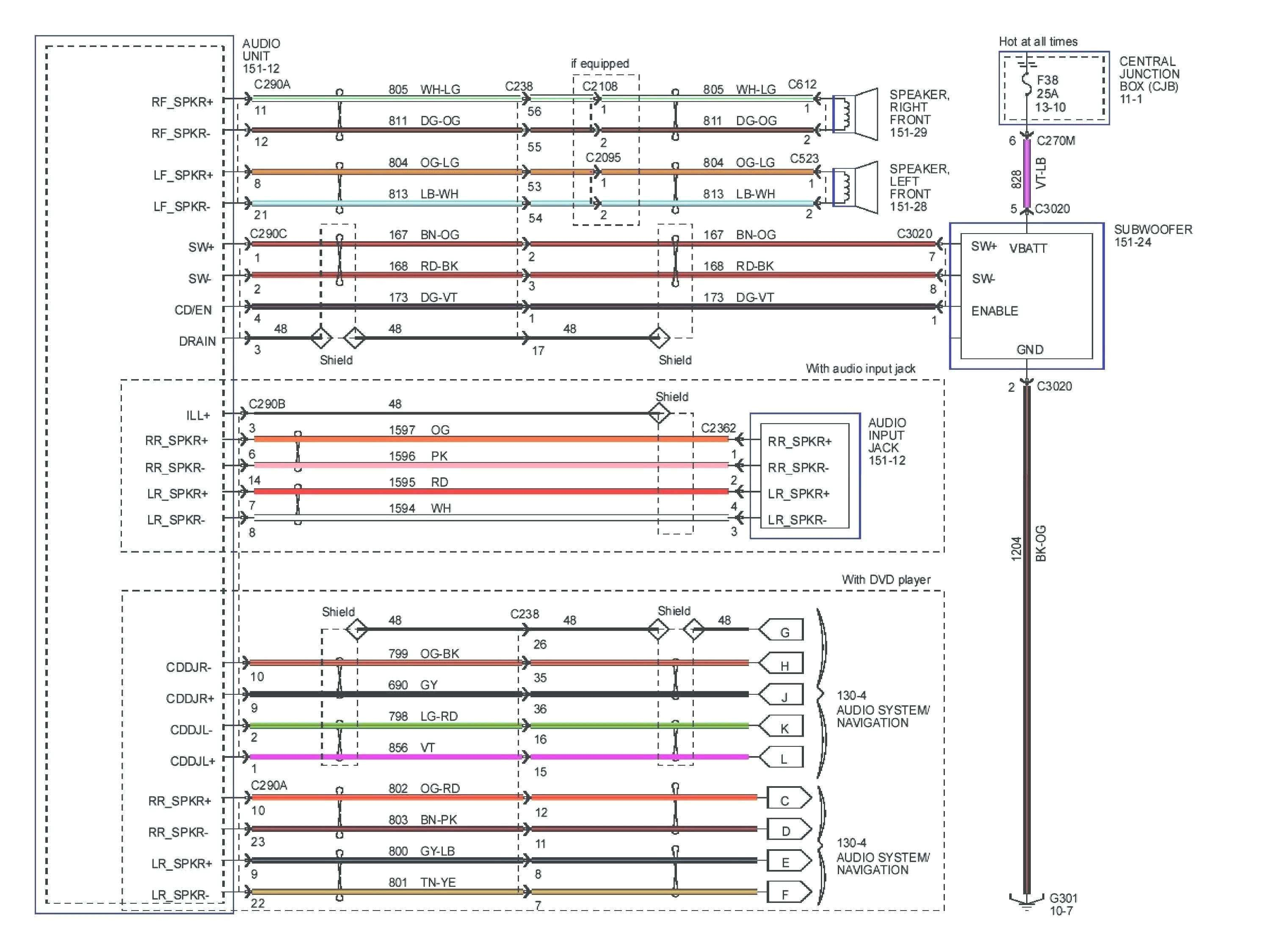
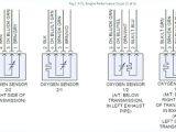
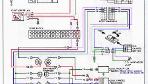
civic o2 sensor wiring diagram wiring library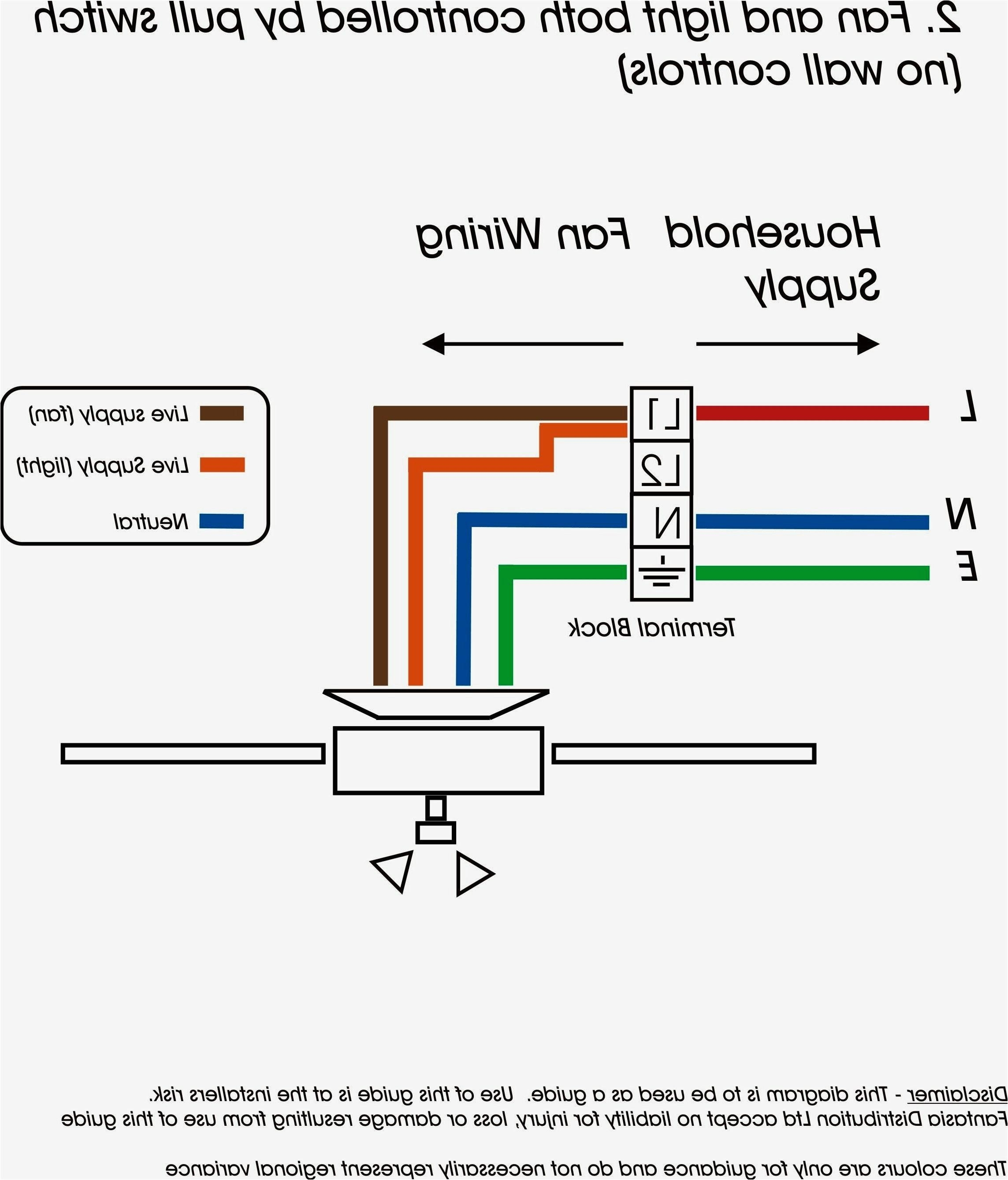
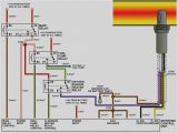
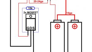
wiring 4 wire o2 sensor furthermore stepper motor driver wiring on 4
o2 sensor wiring diagrams presented here to help you understand the o2 sensor from an electronics and wiring diagram point of view presented using advanced software cg animation technology to help you understand 4 wire oxygen sensor wiring diagram free wiring diagram variety of 4 wire oxygen sensor wiring diagram a wiring diagram is a streamlined standard pictorial depiction of an electrical circuit it reveals the components of the circuit as streamlined forms and also the power as well as signal links between the tools oxygen sensor wiring diagram free wiring diagram assortment of oxygen sensor wiring diagram a wiring diagram is a simplified standard pictorial representation of an electric circuit it shows the components of the circuit as simplified forms and also the power as well as signal links in between the devices o2 sensor diagram honda ridgeline wiring diagram pictures o2 sensor diagram honda ridgeline jul 14 2019 hey dear visitor in todays modern era all information about the expansion of technology is really simple to receive o2 sensor wiring diagram chevy wirings diagram according to previous the lines at a o2 sensor wiring diagram chevy signifies wires at times the wires will cross but it does not mean link between the wires oxygen o2 sensor wiring diagrams 1997 4 6l f150 f250 the 4 6l ford f150 and f250 pickup comes equipped with 4 heated oxygen sensors ho2s this article contains the wiring diagrams of all 4 oxygen sensors how to wire a 4 wire universal oxygen sensor it still runs the four wire universal oxygen sensor is one of the sensors that monitors fuel consumption this sensor measures the amount of unburned oxygen that is present in the oxygen as it exits the vehicle which is indicative of the fuel mixture the four wire universal oxygen sensor must be changed approximately every 60 000 miles and requires a specific wiring process looking for the o2 sensor wiring diagram fixya source o2 sensor wiring diagram for 2004 hyundai sonata there is two wires then suposed to be same color they are not what you looking for but if you have a grey and a black wires it willl be one of those i hope and this help advanced o2 sensor diagnostics tracing sensor wiring and figures 5 and 6 by looking at a wiring diagram here provided by mitchell 1 prodemand we can by simply matching colors figure out which wires belong to the oxygen sensor heater circuit
