Occupancy Sensor Power Pack Wiring Diagram– wiring diagram is a simplified usual pictorial representation of an electrical circuit. It shows the components of the circuit as simplified shapes, and the capability and signal connections amongst the devices.
A wiring diagram usually gives assistance roughly the relative incline and covenant of devices and terminals upon the devices, to back up in building or servicing the device. This is unlike a schematic diagram, where the contract of the components’ interconnections on the diagram usually does not reach agreement to the components’ being locations in the the end device. A pictorial diagram would piece of legislation more detail of the instinctive appearance, whereas a wiring diagram uses a more symbolic notation to bring out interconnections beyond instinctive appearance.
A wiring diagram is often used to troubleshoot problems and to create distinct that all the contacts have been made and that everything is present.
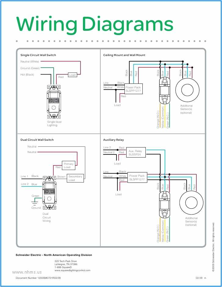
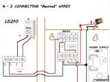
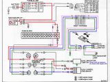
watt stopper relay control panel wiring diagrams wiring diagram local
Architectural wiring diagrams play the approximate locations and interconnections of receptacles, lighting, and permanent electrical services in a building. Interconnecting wire routes may be shown approximately, where particular receptacles or fixtures must be upon a common circuit.
Wiring diagrams use welcome symbols for wiring devices, usually substitute from those used on schematic diagrams. The electrical symbols not lonesome sham where something is to be installed, but also what type of device is mammal installed. For example, a surface ceiling vivacious is shown by one symbol, a recessed ceiling fresh has a alternating symbol, and a surface fluorescent light has unorthodox symbol. Each type of switch has a every other fable and fittingly attain the various outlets. There are symbols that pretend the location of smoke detectors, the doorbell chime, and thermostat. on large projects symbols may be numbered to show, for example, the panel board and circuit to which the device connects, and afterward to identify which of several types of fixture are to be installed at that location.

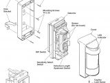
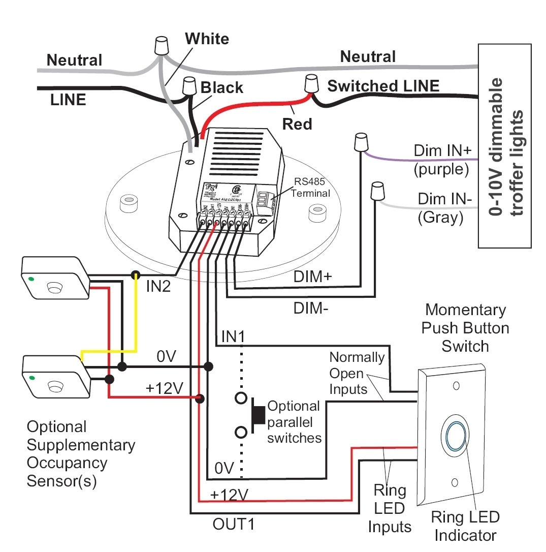
omni ceiling mount vacancy occupancy sensor product line hubbell
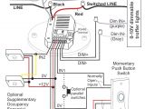
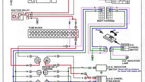
watt stopper dimming wiring diagram my wiring diagram
A set of wiring diagrams may be required by the electrical inspection authority to agree to link of the habitat to the public electrical supply system.
Wiring diagrams will with complement panel schedules for circuit breaker panelboards, and riser diagrams for special facilities such as flame alarm or closed circuit television or additional special services.
You Might Also Like :
- Hopkins Trailer Adapter Wiring Diagram
- 2001 Silverado Tail Light Wiring Diagram
- How to Make A Wiring Diagram
occupancy sensor power pack wiring diagram another image:
watt stopper relay control panel wiring diagrams wiring diagram local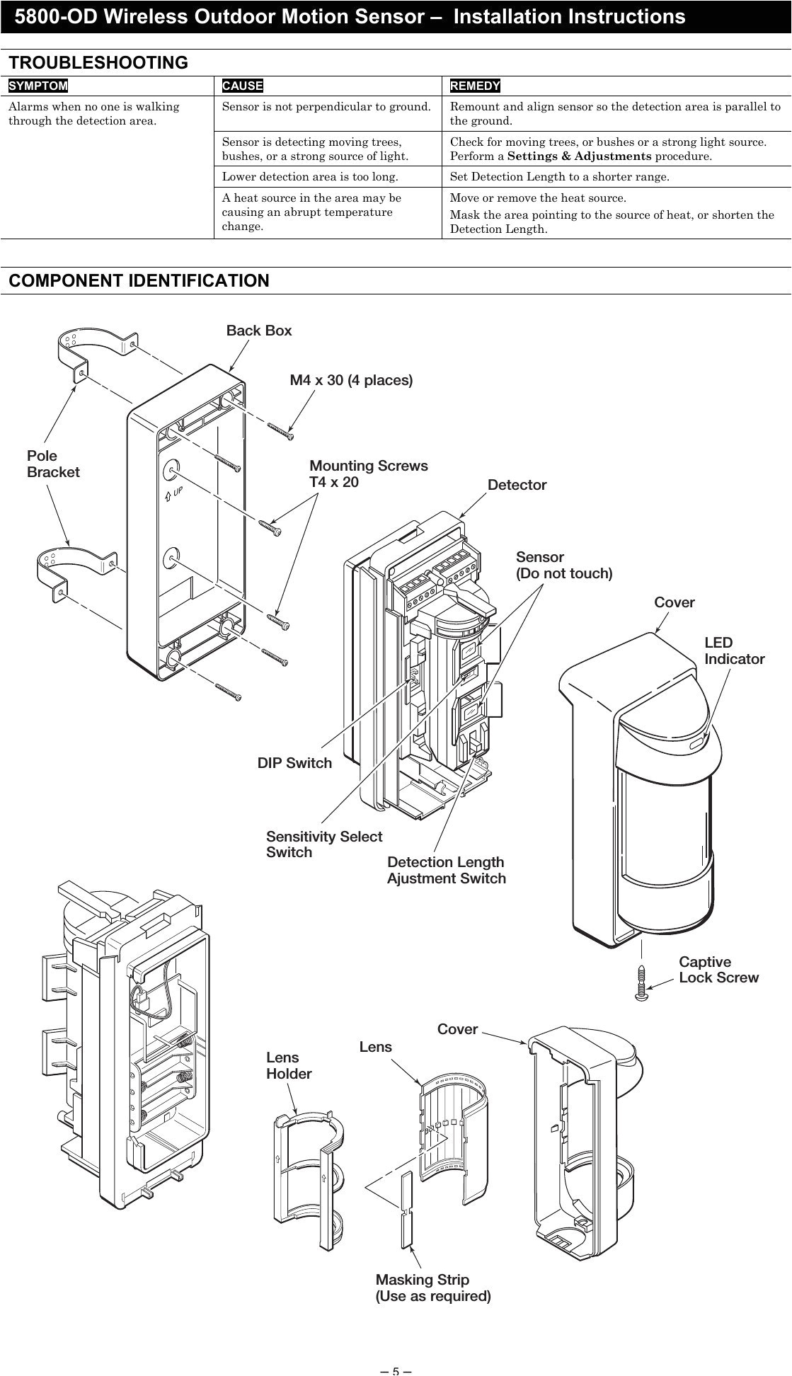
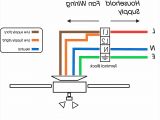
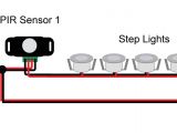
need a diagram of how to wire two low voltage motion detectors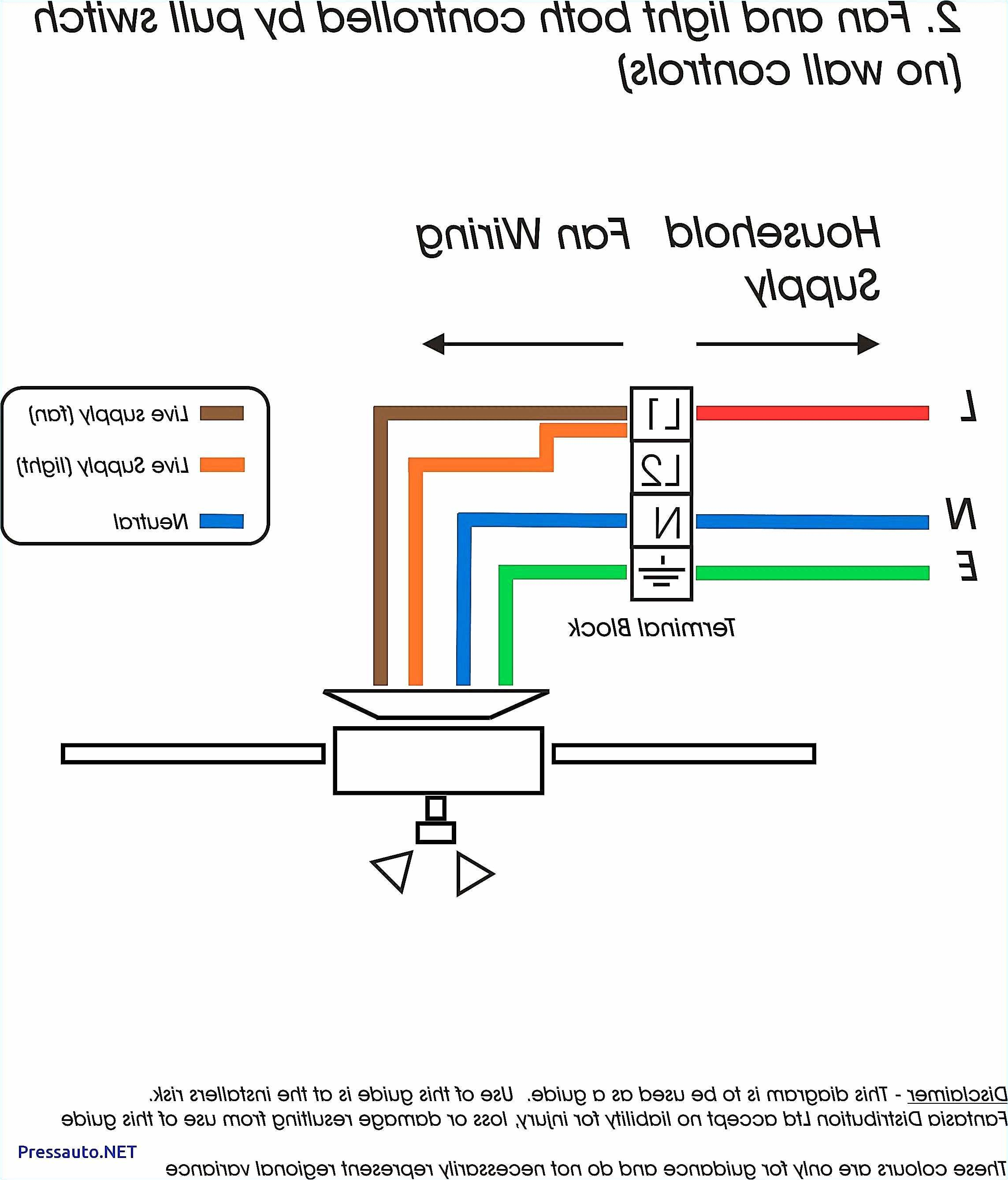
step dimming wiring diagram wiring diagram technic
occupancy sensor power pack wiring diagram free wiring collection of occupancy sensor power pack wiring diagram a wiring diagram is a simplified standard photographic representation of an electric circuit occupancy sensor power pack wiring diagram download occupancy sensor power pack wiring diagram architectural circuitry layouts reveal the approximate places and also interconnections of receptacles lighting and also permanent electric services in a structure pk 93960 10 00 2c occupancy sensor to be installed and or figure 1 figure 2 if permitted by local codes figure 3a wiring diagram 1 multiple sensors single power pack wiring diagram 2 multiple sensors single add a relay occupancy sensor power pack cat no opp20 0d1 auto on the relay in the power pack is controlled by the occupancy sensors connected via the 22 gauge blue auto on occupancy wire and photocells connected via the 22 gauge gray photocell wire for the rd3 rd4 models wattstopper how to wiring a bz 150 universal voltage power pack learn how to correctly wire a bz 150 universal voltage power pack occupancy sensor design and application guide although there are several steps involved in implementing occupancy sensor controls outlined on the following pages this flow chart offers a quick way to determine which sensor technology is best for your application occupancy sensor los c series installation instructions english p n 031260 rev c 03 13 180 field of view 360 field of view occupancy sensor los c series installation instructions description the los c series of ceiling mounted sensors incorporate ultrasonic cus infrared cir and dual wiring schematics hubbell wiring device kellems ceiling sensors wiring scenarios 8 19 daylight harvesting with three circuits with 5 sensors power pack supplies 150ma each power pack supplies 150ma each power pack rated for 20 amps power pack rated for 20 amps slave pack requires 33ma each slave pack contacts rated for 20 amps do not attempt to power more than 4 devices be it sensors or slave packs from a single power pack 4 bz 50 universal voltage power pack legrand the bz 50 universal voltage power pack provides 24 vdc operating voltage to wattstopper s low voltage occupancy sensors the rc version includes an integrated rj45 jack this device is rohs conforming opp20 d1 leviton the leviton opp20 super duty power pack is the first power pack designed to control virtually any lighting or receptacle circuit load to meet today s challenges for solid state lighting control and tougher code requirements for unmatched performance and durability
