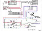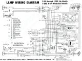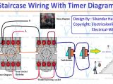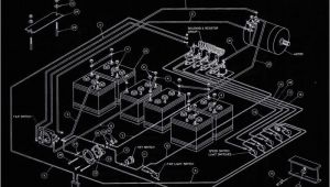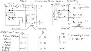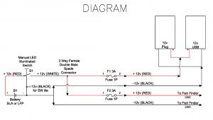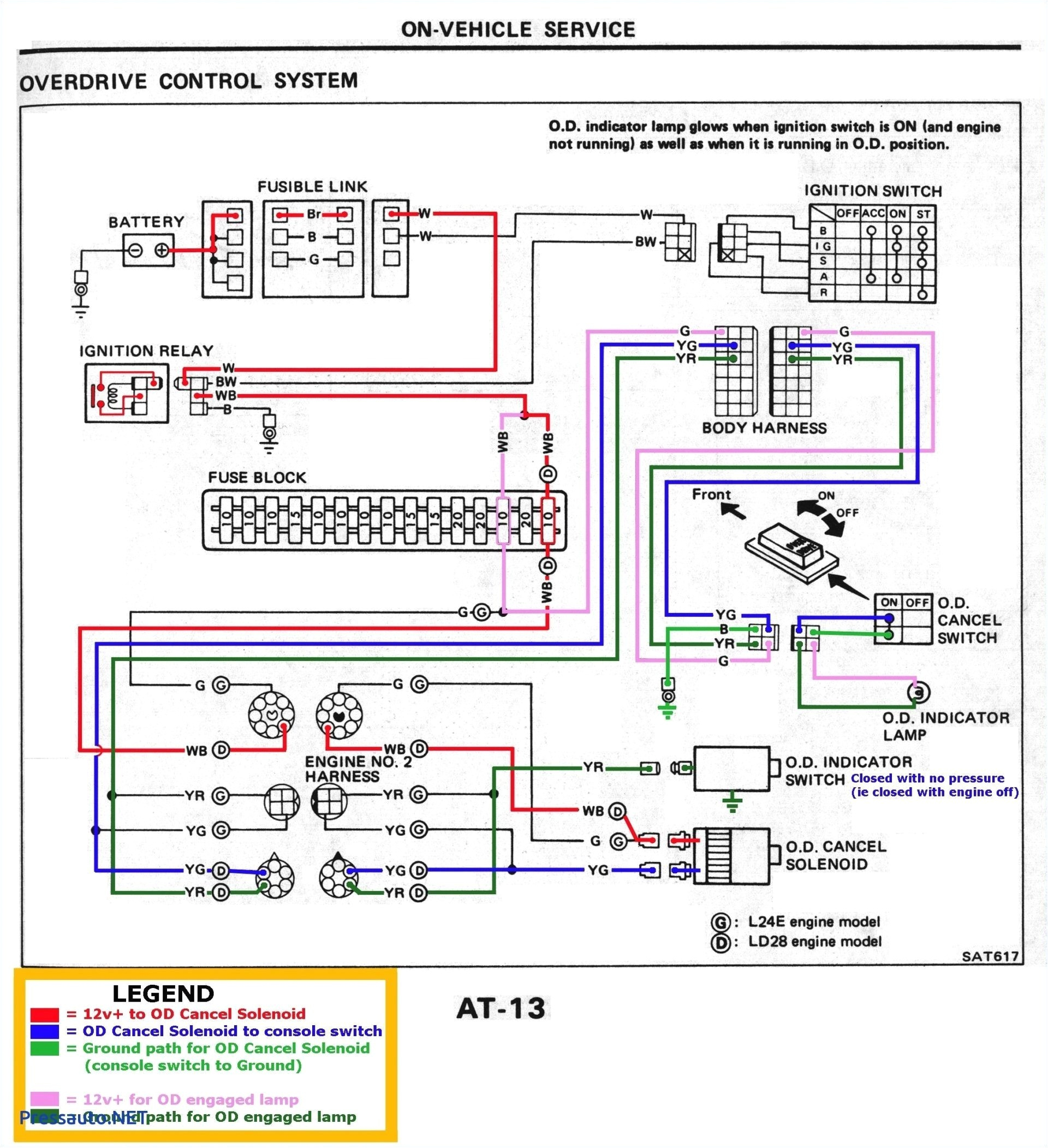
Omron Timer Wiring Diagram– wiring diagram is a simplified good enough pictorial representation of an electrical circuit. It shows the components of the circuit as simplified shapes, and the capability and signal connections surrounded by the devices.
A wiring diagram usually gives opinion more or less the relative incline and arrangement of devices and terminals on the devices, to incite in building or servicing the device. This is unlike a schematic diagram, where the conformity of the components’ interconnections on the diagram usually does not say yes to the components’ being locations in the ended device. A pictorial diagram would exploit more detail of the creature appearance, whereas a wiring diagram uses a more symbolic notation to put the accent on interconnections greater than mammal appearance.
A wiring diagram is often used to troubleshoot problems and to create certain that all the friends have been made and that anything is present.
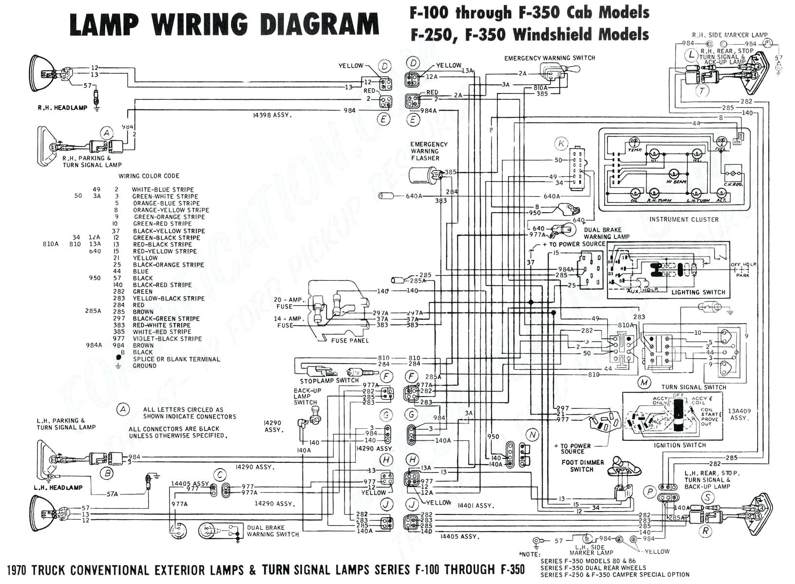
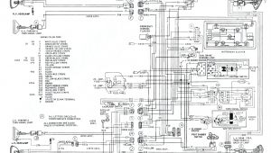
318 engine wire harness diagram wiring diagram name
Architectural wiring diagrams con the approximate locations and interconnections of receptacles, lighting, and remaining electrical services in a building. Interconnecting wire routes may be shown approximately, where particular receptacles or fixtures must be upon a common circuit.
Wiring diagrams use standard symbols for wiring devices, usually substitute from those used upon schematic diagrams. The electrical symbols not by yourself feign where something is to be installed, but with what type of device is being installed. For example, a surface ceiling blithe is shown by one symbol, a recessed ceiling fresh has a exchange symbol, and a surface fluorescent blithe has choice symbol. Each type of switch has a stand-in tale and thus get the various outlets. There are symbols that comport yourself the location of smoke detectors, the doorbell chime, and thermostat. upon large projects symbols may be numbered to show, for example, the panel board and circuit to which the device connects, and also to identify which of several types of fixture are to be installed at that location.
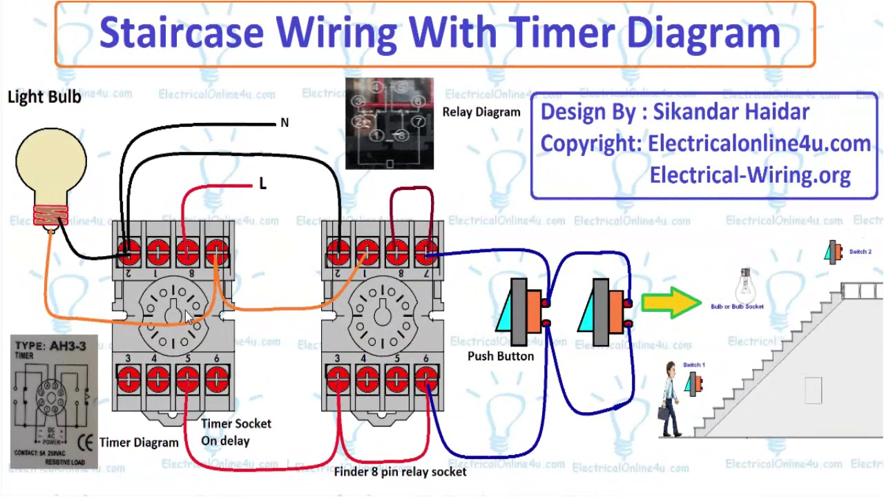
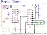
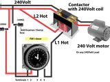
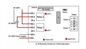
electrical timer wiring diagram wiring diagram number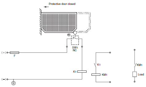
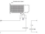
safety circuit examples of safety components technical guide
A set of wiring diagrams may be required by the electrical inspection authority to agree to relationship of the residence to the public electrical supply system.
Wiring diagrams will next enlarge panel schedules for circuit breaker panelboards, and riser diagrams for special facilities such as flare alarm or closed circuit television or extra special services.
You Might Also Like :
[gembloong_related_posts count=3]
omron timer wiring diagram another picture:
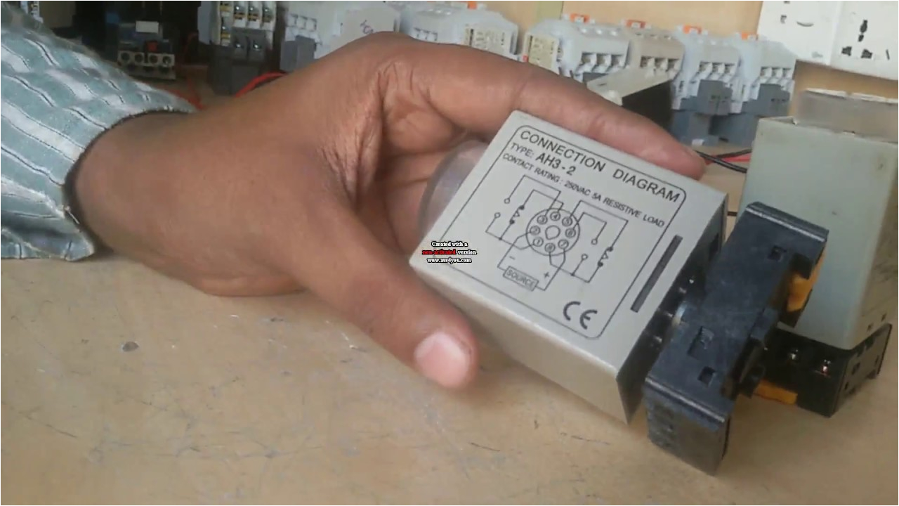
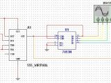
timer connection how to make single timer to twin timer youtube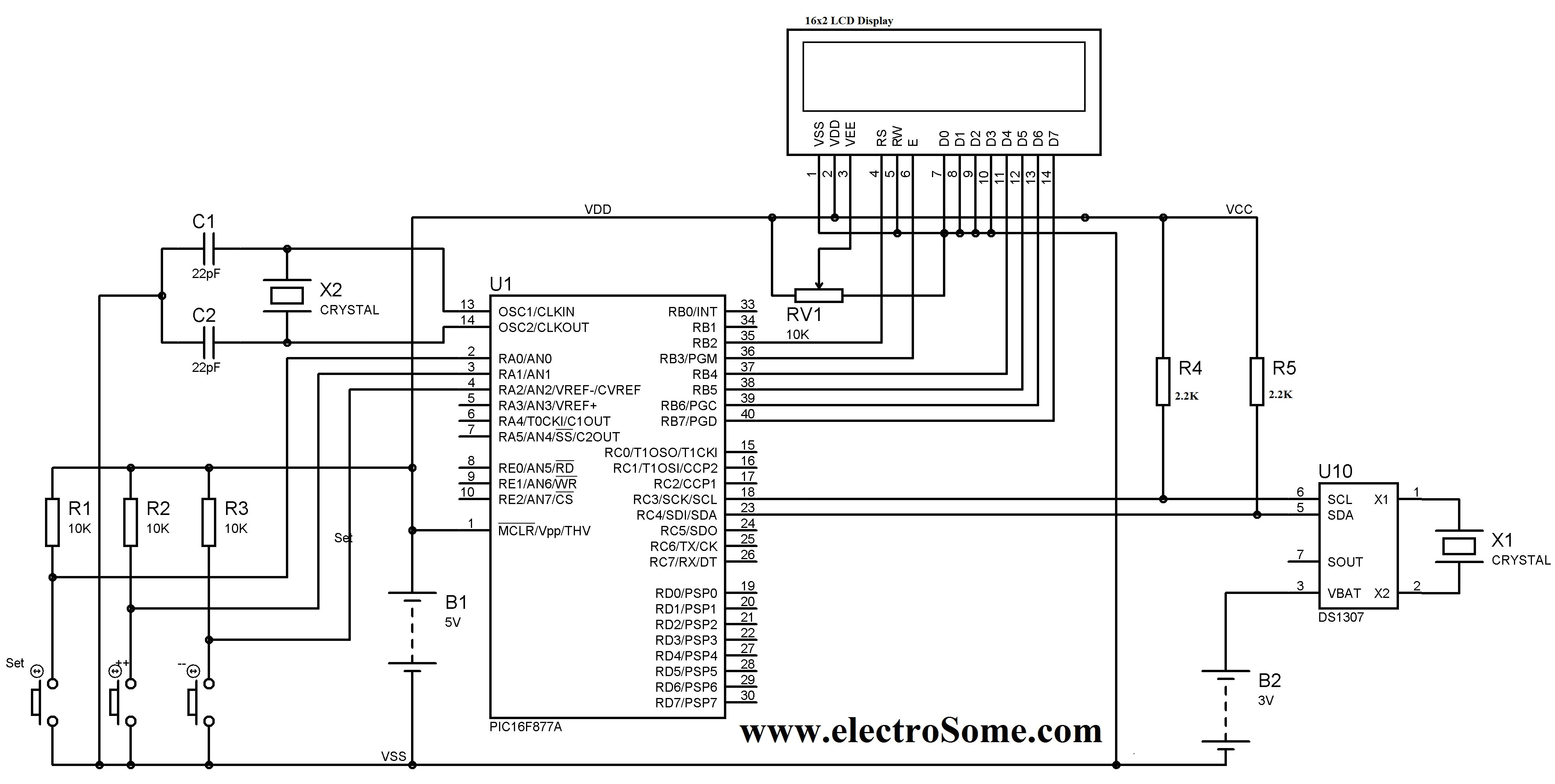
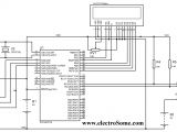
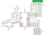
digital clock with alarm ds1307 alarm digital clock circuit diagram
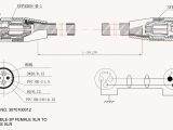
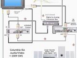
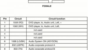
avi to rca wiring diagram wiring diagram technic
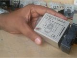
solid state timer h3cr limasoft cz h3cr h3cr 3 timing charts in the schematic diagrams each thick line indicates the external wiring shaded areas show internal connections h3cr a h3cr as six function timers omron h3cr a8 wiring diagram free wiring diagram variety of omron h3cr a8 wiring diagram a wiring diagram is a simplified conventional photographic representation of an electric circuit it reveals the parts of the circuit as simplified forms as well as the power as well as signal links in between the tools omron timer wire diagram wiring diagram pictures omron timer wire diagram jun 23 2019 welcome to wiring diagram pictures lots of people have used on line to find facts guidelines articles or another resource for their purposes omron h3ca a wiring diagram free wiring diagram variety of omron h3ca a wiring diagram a wiring diagram is a simplified conventional photographic depiction of an electrical circuit it shows the components of the circuit as simplified shapes and the power and also signal connections between the tools model selection guide for timers omron a timer is a control device that outputs a signal at a preset time after an input signal is received basic configuration 1 the electronic circuits receive an input and measure time zen programmable relay operation manual omron iv preface omron products are manufactured for use according to proper procedures by a qualified operator and only for the purposes described in this manual omron h3ca solid state timer farnell element14 h3ca a 3 1 6 2 4 5 9 8 7 reset start com 11 10 supply voltage can be either a ac or dc source pins 8 9 and 11 are terminals for the timer s internal output relay help me wire up an omron h3y 2 delay timer all about it has been a decade or so since i ve used these but here goes the power voltage must be on for the duration of the cycle once power is applied the timer circuit will operate omron h5cx manual pdf download page 22 timing diagram set value down output mode a 3 power on delay 2 timer does not reset when power comes on timing starts when the reset input goes off power the start signal disables the timing function i e same function as the gate input timers product category omron industrial automation omron provides a range of analog timers and digital timers as well as time switches for 24 hour weekly or annual time control
