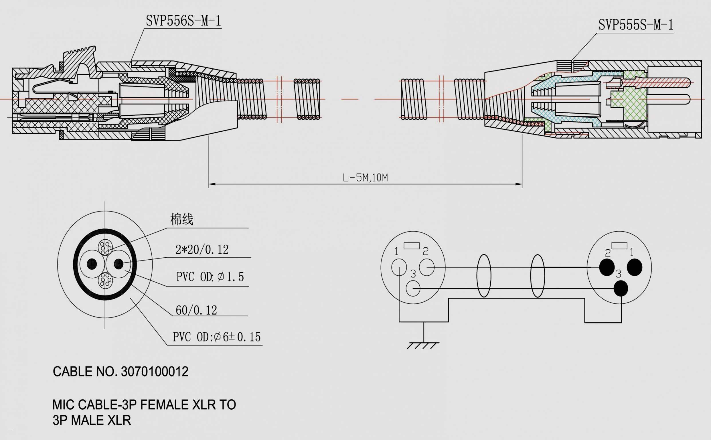
Patch Panel Wiring Diagram– wiring diagram is a simplified pleasing pictorial representation of an electrical circuit. It shows the components of the circuit as simplified shapes, and the capability and signal connections in the midst of the devices.
A wiring diagram usually gives guidance roughly the relative aim and harmony of devices and terminals on the devices, to support in building or servicing the device. This is unlike a schematic diagram, where the contract of the components’ interconnections on the diagram usually does not reach agreement to the components’ monster locations in the done device. A pictorial diagram would take steps more detail of the innate appearance, whereas a wiring diagram uses a more symbolic notation to bring out interconnections over mammal appearance.
A wiring diagram is often used to troubleshoot problems and to make determined that every the contacts have been made and that everything is present.
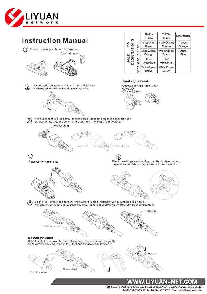
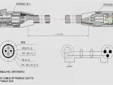
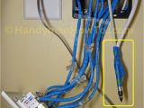
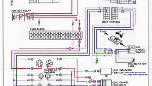
telephone patch panel wiring diagram wiring diagram centre
Architectural wiring diagrams law the approximate locations and interconnections of receptacles, lighting, and unshakable electrical services in a building. Interconnecting wire routes may be shown approximately, where particular receptacles or fixtures must be on a common circuit.
Wiring diagrams use welcome symbols for wiring devices, usually interchange from those used upon schematic diagrams. The electrical symbols not and no-one else operate where something is to be installed, but after that what type of device is bodily installed. For example, a surface ceiling light is shown by one symbol, a recessed ceiling roomy has a stand-in symbol, and a surface fluorescent spacious has other symbol. Each type of switch has a substitute story and consequently attain the various outlets. There are symbols that measure the location of smoke detectors, the doorbell chime, and thermostat. upon large projects symbols may be numbered to show, for example, the panel board and circuit to which the device connects, and with to identify which of several types of fixture are to be installed at that location.
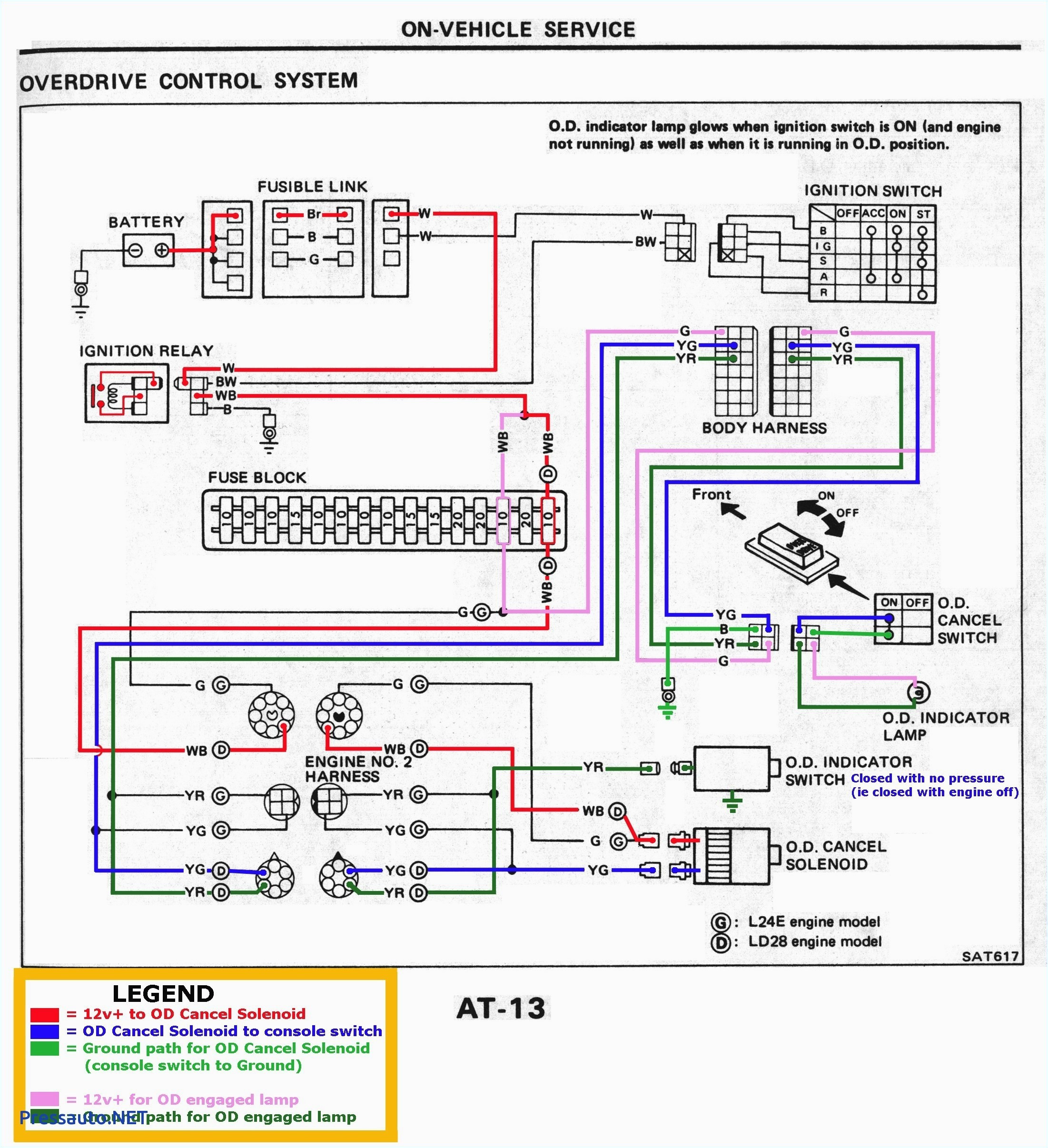
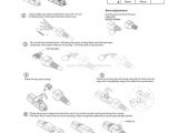
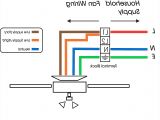
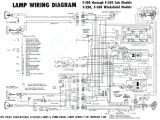
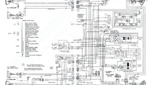
wiring panel diagram wiring diagram used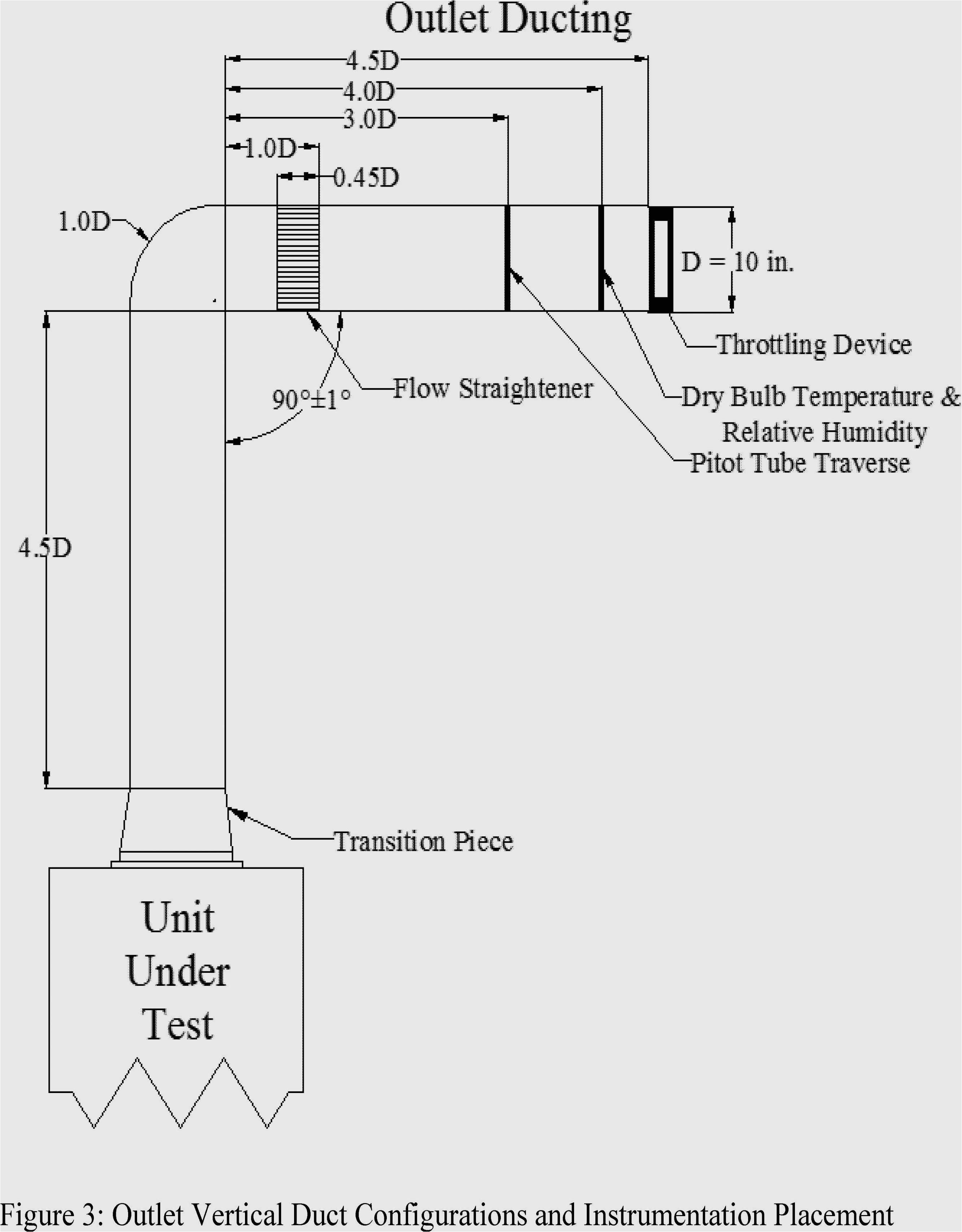
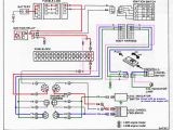
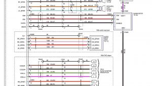
wire diagram shapes wiring diagram val
A set of wiring diagrams may be required by the electrical inspection authority to take up attachment of the habitat to the public electrical supply system.
Wiring diagrams will furthermore append panel schedules for circuit breaker panelboards, and riser diagrams for special facilities such as flame alarm or closed circuit television or supplementary special services.
You Might Also Like :
[gembloong_related_posts count=3]
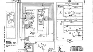
patch panel wiring diagram another graphic:
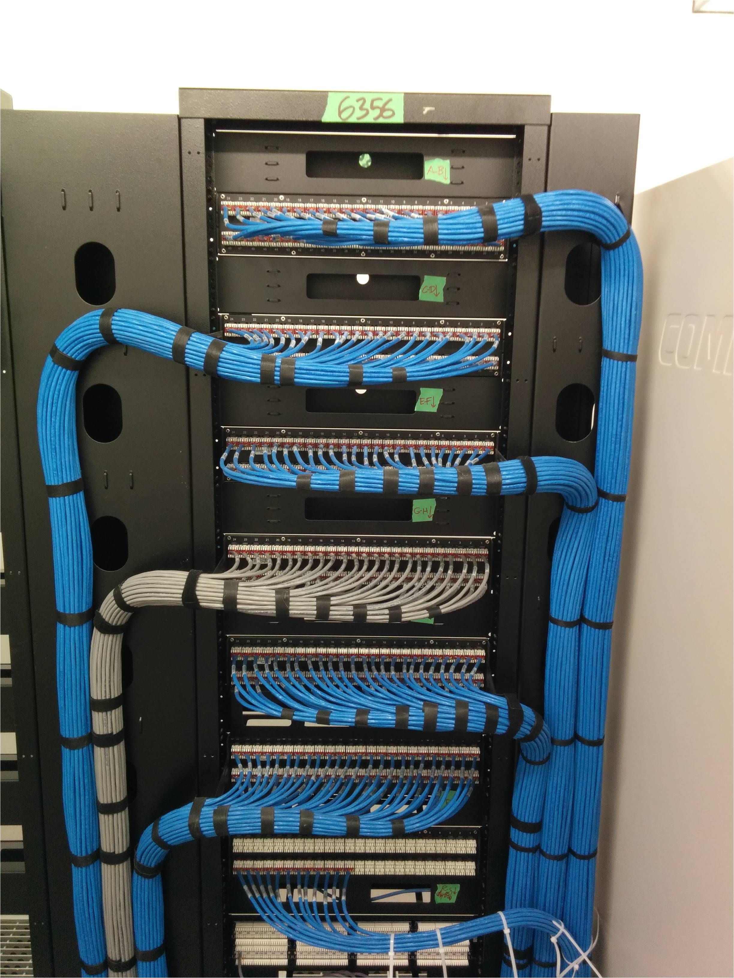
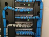
network cable management on pinterest ethernet wiring cable and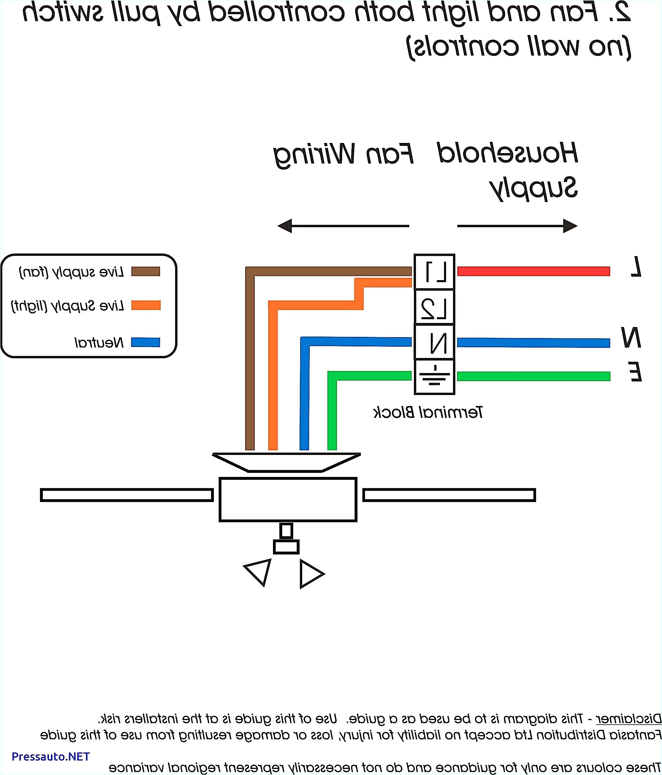
cabac rj45 wiring diagram data diagram schematic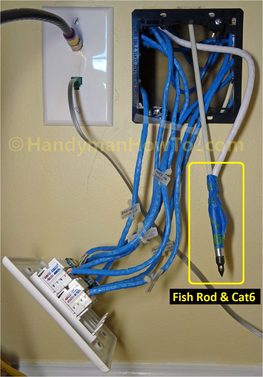
network cable management on pinterest ethernet wiring cable and
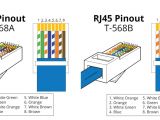
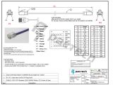
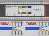
how to punch wires into patch panels monoprice cat6 patch panel punch down tutorial shop networking solutions https goo gl prvrk8 leviton cat5e patch panel wiring diagram free wiring diagram assortment of leviton cat5e patch panel wiring diagram a wiring diagram is a streamlined conventional photographic depiction of an electric circuit t568b wiring diagram patch panel free wiring diagram collection of t568b wiring diagram patch panel a wiring diagram is a simplified traditional photographic representation of an electrical circuit cat6 patch panel wiring diagram wiring diagram chart cat6 patch panel wiring diagram patch panel wiring diagram and 0005279 cat 5e 48 port 2 rms wiring cat6 patch panel wiring diagram how to punch wires into patch panels youtube cat6 patch panel wiring diagram monoprice 48 port cat6 patch panel 110 type 568a b compatible cat5 patch panel wiring diagram wiring diagram chart cat5 patch panel wiring diagram see more about cat5 patch panel wiring diagram cat5 patch cable wiring diagram cat5 patch panel wiring diagram how to wire rj45 patch panels for home phone lines you can create flexible multi line telephone wiring using cat5 or cat6 rj45 patch panels here s some tips on how to wire rj45 patch panels for telephone wiring cat5e wiring cat5e patch panel wiring how to wire a this article will mainly introduce cat5e patch panels and show you cat5e patch panel wiring steps cat5e patch cable the cat5e patch cable is the basic component to connect end devices to patch panel ports and to connect the ports between two local patch panels solved patch panel to switch connections networking our patch panel 48 ports are laid out across first and then down ports 1 24 on the top and 25 48 on the bottom the netgear switches were laid out the same way and it was easy using our 1ft patch cable to go from port to port the hp s are laid out with all odd numbers across the top and even numbers across the bottom installing cable and terminating a patch panel part 1 of 4 installing cable and terminating a patch panel part 1 of 4 cablesupply com loading unsubscribe from cablesupply com cancel unsubscribe working subscribe subscribed unsubscribe 44k category 5 5e cat 6 cabling tutorial and faq s the back of the patch panel also shows both wiring methods as seen below the upper diagram is 568a and the lower diagram is 568b notice that the blue and brown pairs are identical for both methods
