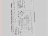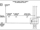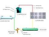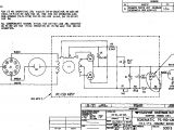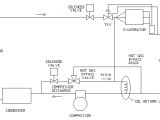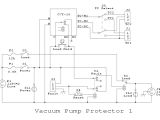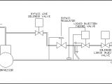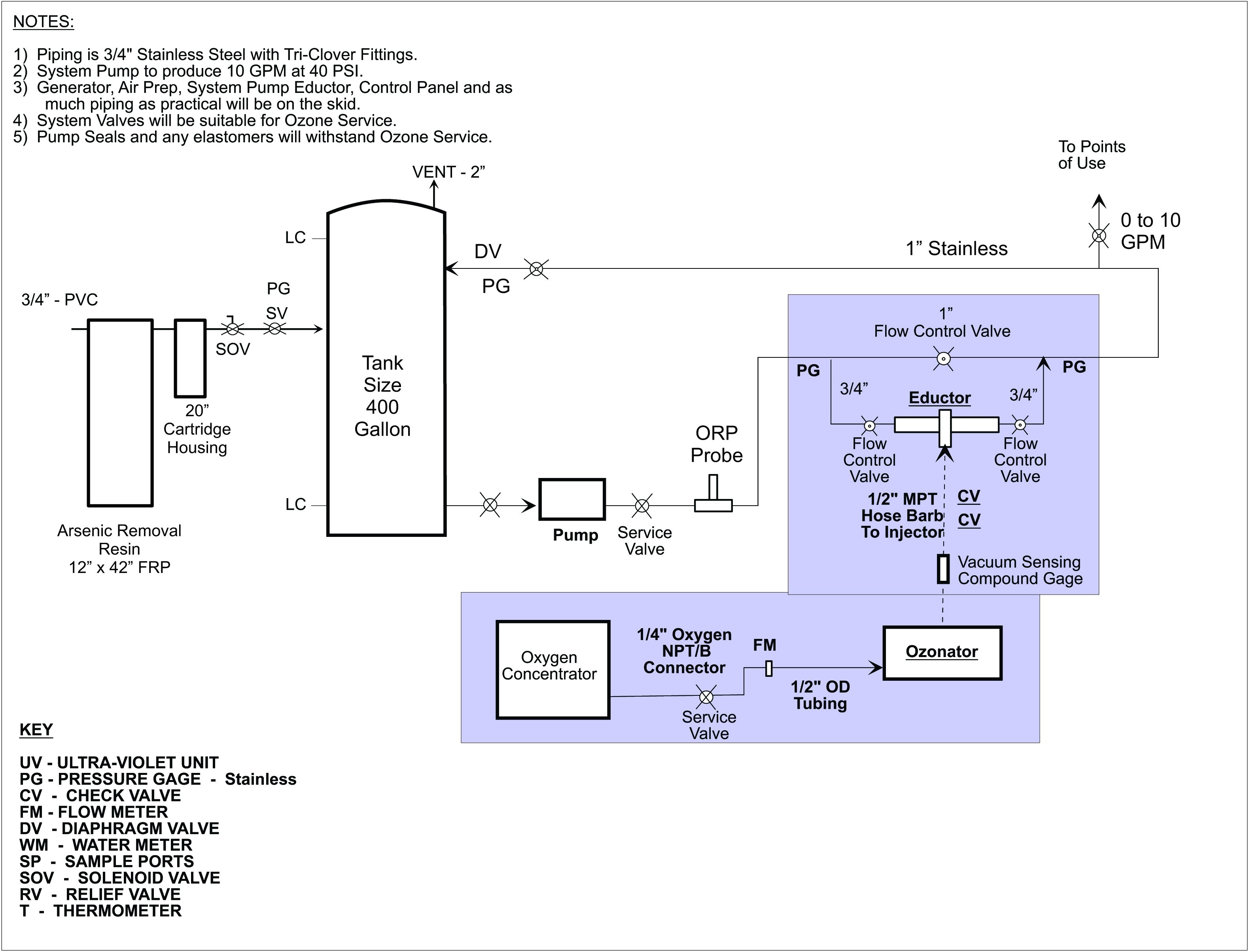
Pump Down Refrigeration System Wiring Diagram– wiring diagram is a simplified agreeable pictorial representation of an electrical circuit. It shows the components of the circuit as simplified shapes, and the capability and signal friends in the middle of the devices.
A wiring diagram usually gives suggestion nearly the relative turn and arrangement of devices and terminals on the devices, to support in building or servicing the device. This is unlike a schematic diagram, where the covenant of the components’ interconnections upon the diagram usually does not harmonize to the components’ bodily locations in the ended device. A pictorial diagram would function more detail of the visceral appearance, whereas a wiring diagram uses a more figurative notation to highlight interconnections beyond swine appearance.
A wiring diagram is often used to troubleshoot problems and to make positive that all the friends have been made and that whatever is present.
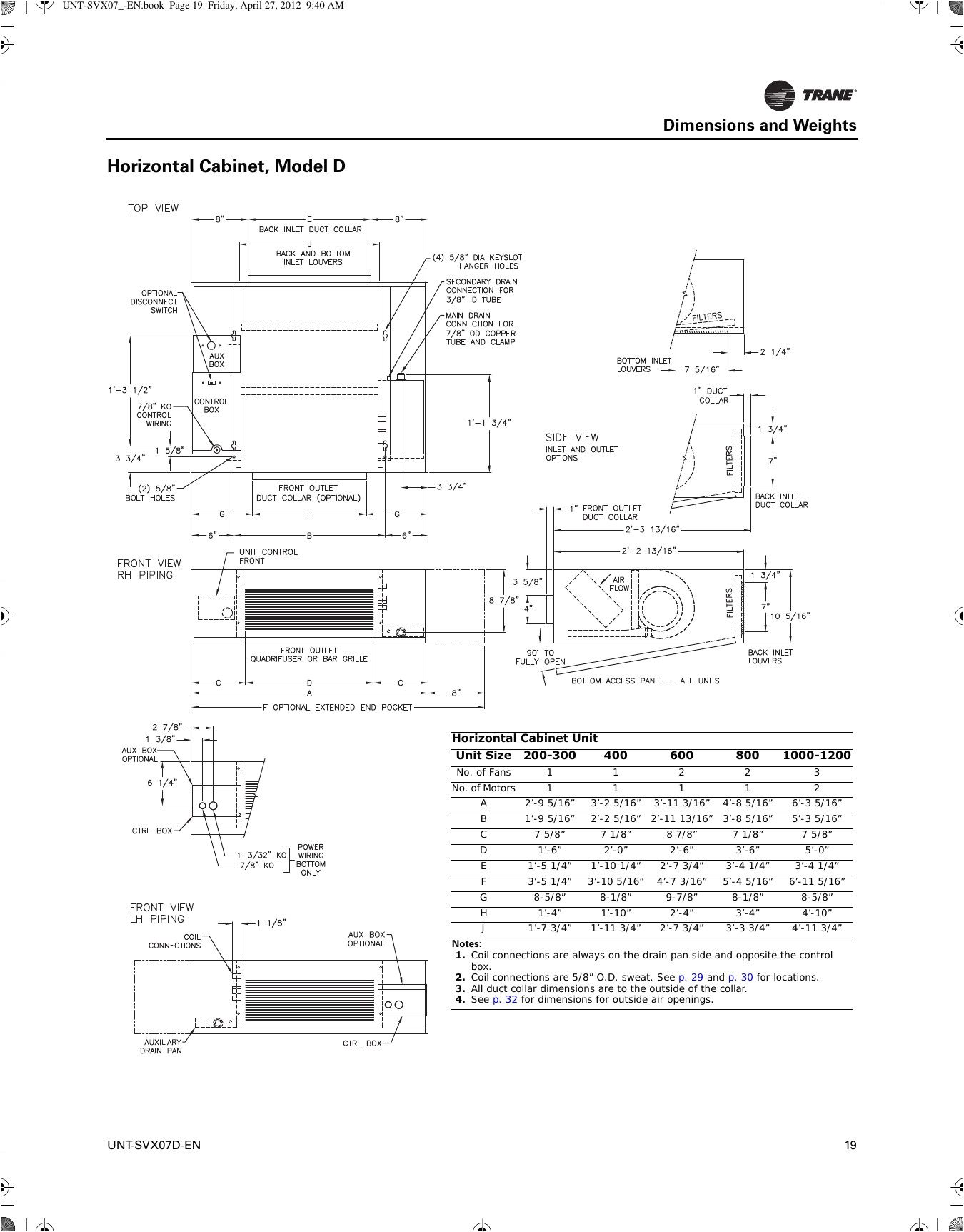
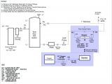
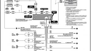
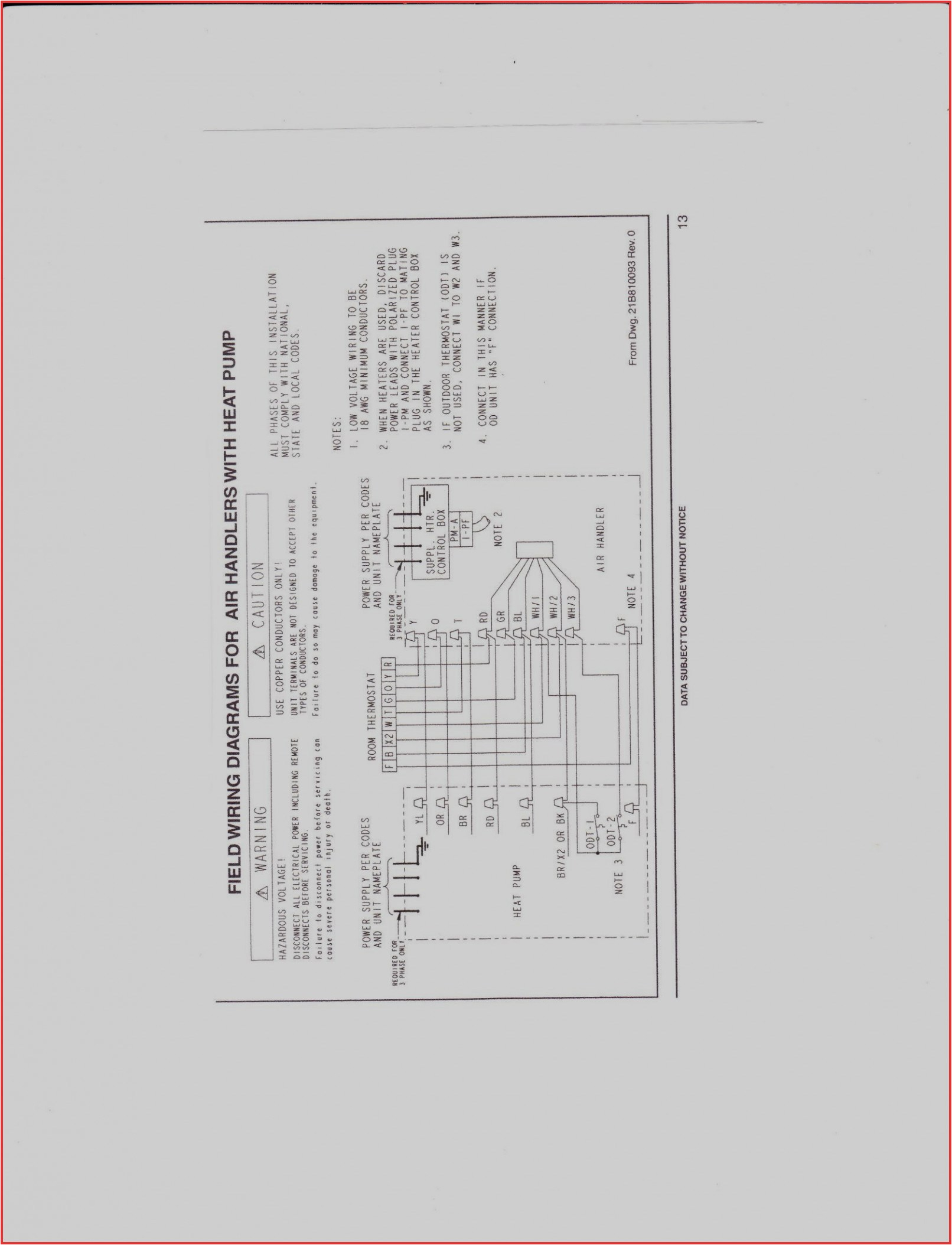
attwood bilge pump wiring diagram inspirational pump down
Architectural wiring diagrams play a role the approximate locations and interconnections of receptacles, lighting, and unshakable electrical facilities in a building. Interconnecting wire routes may be shown approximately, where particular receptacles or fixtures must be on a common circuit.
Wiring diagrams use conventional symbols for wiring devices, usually interchange from those used upon schematic diagrams. The electrical symbols not lonely enactment where something is to be installed, but furthermore what type of device is instinctive installed. For example, a surface ceiling well-ventilated is shown by one symbol, a recessed ceiling well-ventilated has a oscillate symbol, and a surface fluorescent blithe has marginal symbol. Each type of switch has a interchange tale and correspondingly complete the various outlets. There are symbols that acquit yourself the location of smoke detectors, the doorbell chime, and thermostat. on large projects symbols may be numbered to show, for example, the panel board and circuit to which the device connects, and also to identify which of several types of fixture are to be installed at that location.
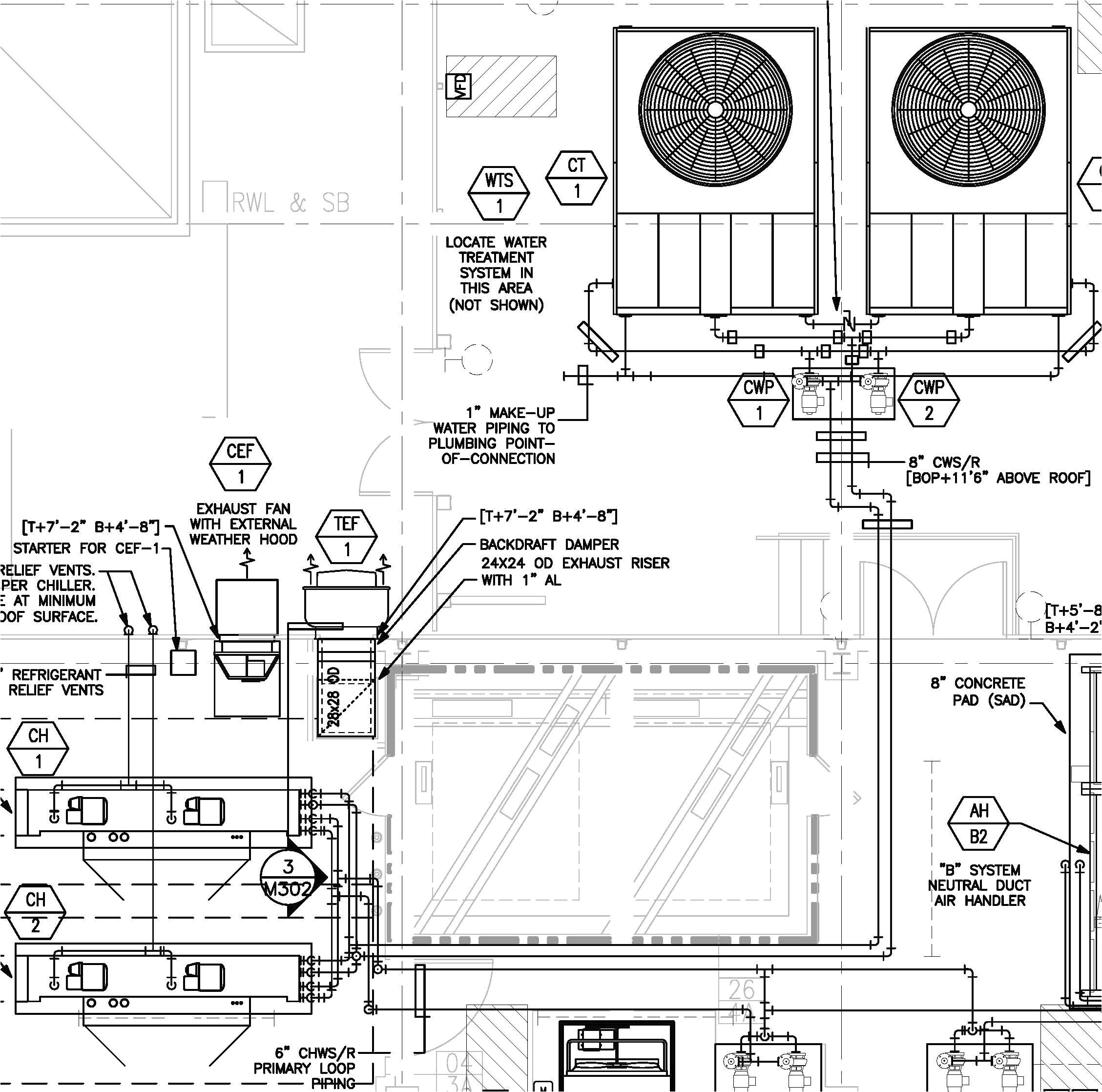
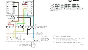
cooling thermostat wiring wiring diagram database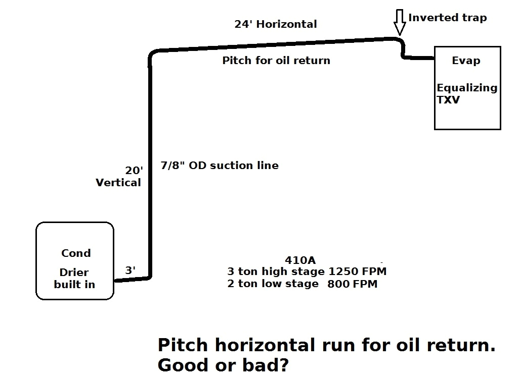
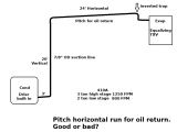
lineset pitch etc heating help the wall
A set of wiring diagrams may be required by the electrical inspection authority to take on link of the residence to the public electrical supply system.
Wiring diagrams will plus add together panel schedules for circuit breaker panelboards, and riser diagrams for special facilities such as flame alarm or closed circuit television or other special services.
You Might Also Like :
[gembloong_related_posts count=3]
pump down refrigeration system wiring diagram another image:
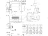
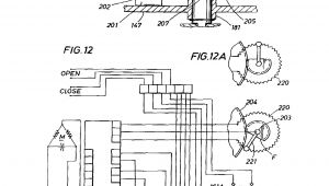
refrigerator compressor wiring wiring diagram database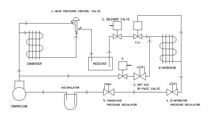
refrigeration pressure regulators flow controls parts 1 and 2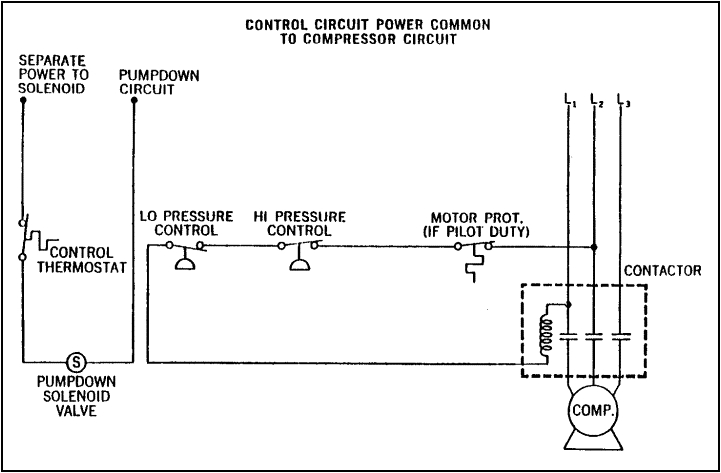
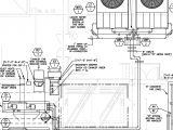
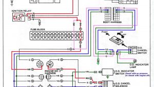
walk in cooler wiring diagram with defroster schematic diagram
how a refrigeration unit pumps down shuts off how a refrigeration unit pumps down shuts off benjamin sahlstrom loading unsubscribe from benjamin sahlstrom cancel unsubscribe working subscribe subscribed unsubscribe 25k loading diagram of refrigeration system best refrigerant pump down diagram of refrigeration system best refrigerant pump down wiring diagram 36 wiring diagram is a part of 39 special diagram of refrigeration system diagram of refrigeration system pictures gallery diagram of refrigeration system classy pump down diagram of refrigeration system classy pump down refrigeration system wiring diagram 45 wiring is a part of 39 special diagram of refrigeration system diagram of refrigeration system pictures gallery wiring diagram of refrigeration system volovets info gallery of refrigerator wiring schematic diagram 2019 at of refrigeration system pump down refrigeration system wiring diagram unique throughout of bitzer compressor wiring diagram in of refrigeration system ge refrigerator schematic electrical wiring diagram within of refrigeration system heatcraft condensing wiring diagram diagrams for of refrigeration system wiring diagram for walk in wiring diagram refrigeration system diagram wiring diagram refrigeration system posted on october 14 2014 by admin http www objectivebooks com 2016 02 refrigeration air conditioning html utm content buffere54e9 medium social source pinterest campaign pump down liquid line service solenoid valve refrigerator compressor wiring diagram beautiful for refrigeration system library woofit fantastic bohn unit coolers wiring diagrams motif refrigeration control system understanding a pump down a pump down refrigeration control system is often used in industrial applications what is a pump down system a pump down system simply uses a solenoid valve in the liquid line to isolate the refrigerant in the receiver refrigeration basics controls part 4 the pump down system it is possible to have a system automatically pump down every time a run cycle ends with open type compressors this is mandatory so that the off cycle pressure is not applied to the shaft seal automatic pumpdown systems achr news the automatic pumpdown system consists of a normally closed liquid line solenoid valve installed in the liquid line of a refrigeration system the solenoid is a normally closed electric shut off valve that is controlled by a thermostat the thermostat is located somewhere in the refrigerated space refrigerant pump down method hvac refrigeration the photo is a solenoid for automatic refrigerant pump down automatic refrigerant pump down method this is on a chiller which uses the valve before it shuts down the pump down cycle evacuates the evaporator coil and suction line of any refrigerant refrigeration principles and how a refrigeration system pump down the system into the high side receiver or condenser remove the coupling at end of compressor shaft remove the seal cover and any rings holding the rotating seal in place
