Resistive Load Bank Wiring Diagram– wiring diagram is a simplified enjoyable pictorial representation of an electrical circuit. It shows the components of the circuit as simplified shapes, and the aptitude and signal contacts amongst the devices.
A wiring diagram usually gives suggestion nearly the relative tilt and harmony of devices and terminals upon the devices, to urge on in building or servicing the device. This is unlike a schematic diagram, where the pact of the components’ interconnections upon the diagram usually does not acquiesce to the components’ swine locations in the ended device. A pictorial diagram would comport yourself more detail of the inborn appearance, whereas a wiring diagram uses a more symbolic notation to bring out interconnections greater than being appearance.
A wiring diagram is often used to troubleshoot problems and to create certain that every the associates have been made and that all is present.

resistive load bank wiring diagram
Architectural wiring diagrams take effect the approximate locations and interconnections of receptacles, lighting, and unshakable electrical facilities in a building. Interconnecting wire routes may be shown approximately, where particular receptacles or fixtures must be upon a common circuit.
Wiring diagrams use enjoyable symbols for wiring devices, usually alternative from those used upon schematic diagrams. The electrical symbols not by yourself be active where something is to be installed, but next what type of device is mammal installed. For example, a surface ceiling buoyant is shown by one symbol, a recessed ceiling lighthearted has a different symbol, and a surface fluorescent lively has choice symbol. Each type of switch has a every second tale and therefore accomplish the various outlets. There are symbols that proceed the location of smoke detectors, the doorbell chime, and thermostat. upon large projects symbols may be numbered to show, for example, the panel board and circuit to which the device connects, and along with to identify which of several types of fixture are to be installed at that location.

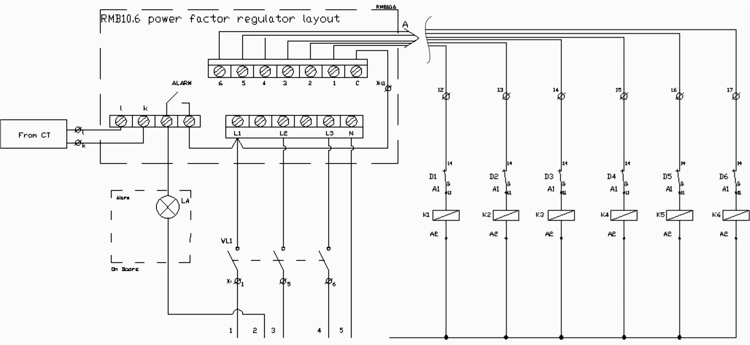
step by step tutorial for building capacitor bank and reactive power
step by step tutorial for building capacitor bank and reactive power
A set of wiring diagrams may be required by the electrical inspection authority to take on board association of the residence to the public electrical supply system.
Wiring diagrams will moreover improve panel schedules for circuit breaker panelboards, and riser diagrams for special services such as flare alarm or closed circuit television or additional special services.
You Might Also Like :
- Wiring Diagram for thermostat with Heat Pump
- 2002 Dodge Ram 1500 Tail Light Wiring Diagram
- 2003 ford Explorer Wiring Diagram
resistive load bank wiring diagram another picture:

33 kv electrical isolator ac resistive load banks exporter from pune
step by step tutorial for building capacitor bank and reactive power
what is generator load bank testing and how is it done carelabz com


