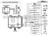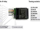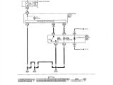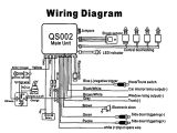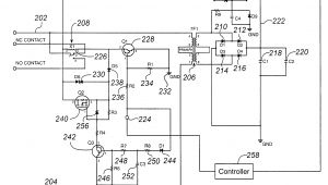
Smart Relay Wiring Diagram– wiring diagram is a simplified suitable pictorial representation of an electrical circuit. It shows the components of the circuit as simplified shapes, and the capacity and signal associates amongst the devices.
A wiring diagram usually gives guidance about the relative position and treaty of devices and terminals on the devices, to put up to in building or servicing the device. This is unlike a schematic diagram, where the arrangement of the components’ interconnections on the diagram usually does not be of the same mind to the components’ mammal locations in the ended device. A pictorial diagram would bill more detail of the monster appearance, whereas a wiring diagram uses a more symbolic notation to put the accent on interconnections over being appearance.
A wiring diagram is often used to troubleshoot problems and to create sure that all the associates have been made and that everything is present.
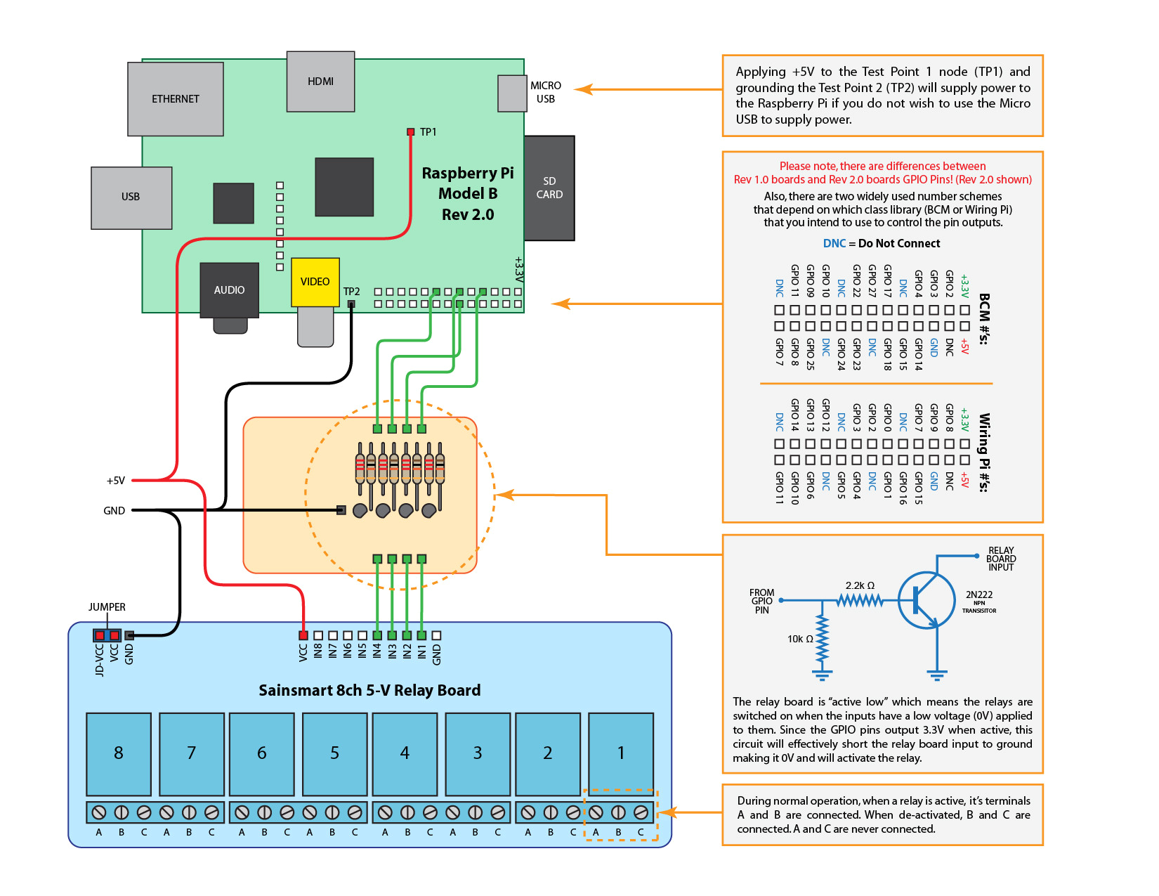
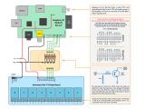
how to wire a raspberry pi to a sainsmart 5v relay board raspberry
Architectural wiring diagrams act out the approximate locations and interconnections of receptacles, lighting, and surviving electrical facilities in a building. Interconnecting wire routes may be shown approximately, where particular receptacles or fixtures must be upon a common circuit.
Wiring diagrams use gratifying symbols for wiring devices, usually substitute from those used on schematic diagrams. The electrical symbols not lonely law where something is to be installed, but plus what type of device is physical installed. For example, a surface ceiling blithe is shown by one symbol, a recessed ceiling buoyant has a every other symbol, and a surface fluorescent spacious has choice symbol. Each type of switch has a substitute fable and hence do the various outlets. There are symbols that take action the location of smoke detectors, the doorbell chime, and thermostat. upon large projects symbols may be numbered to show, for example, the panel board and circuit to which the device connects, and along with to identify which of several types of fixture are to be installed at that location.
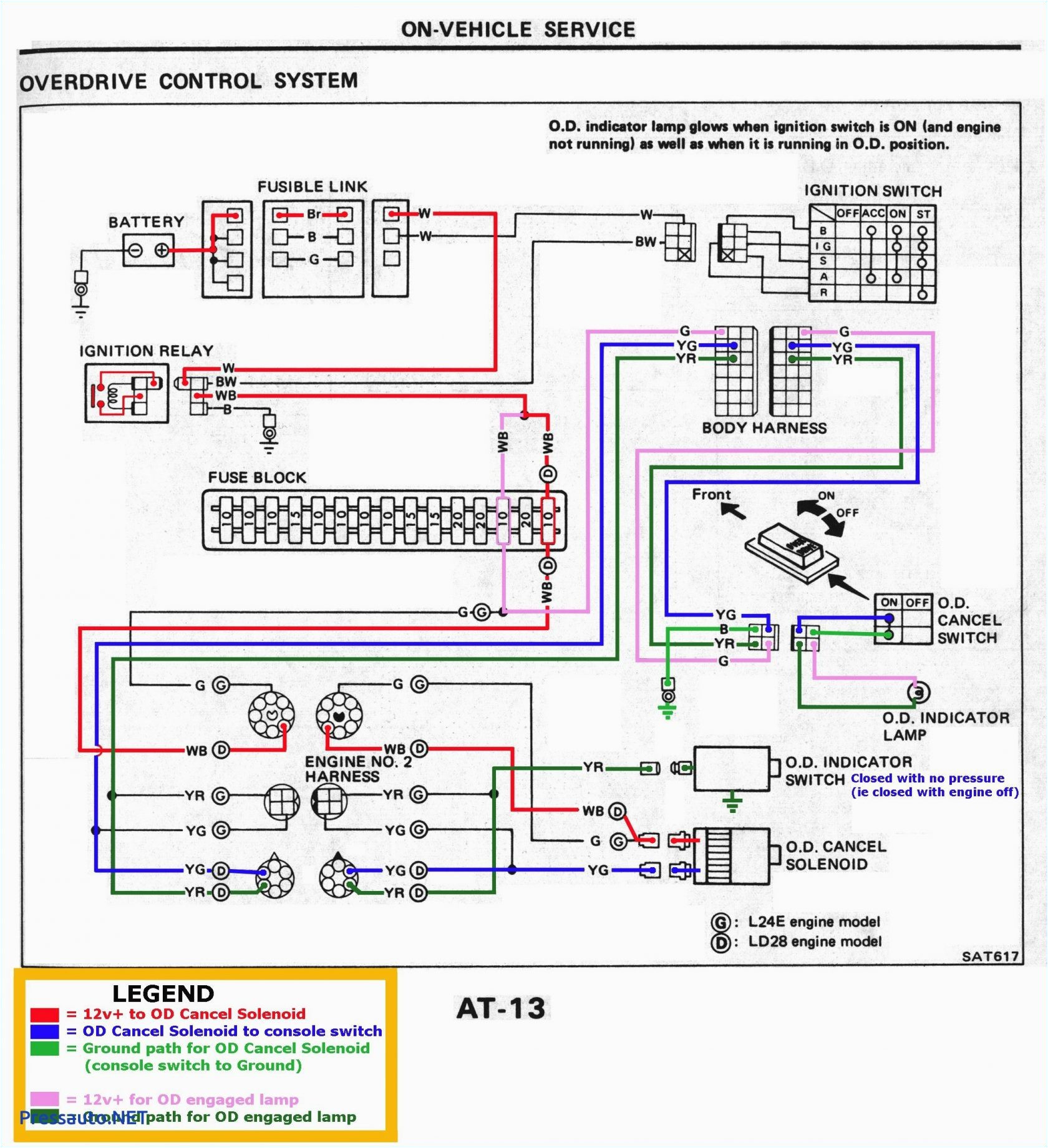
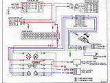
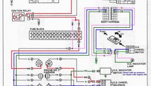
car stereo tocado wiring diagram wiring diagram user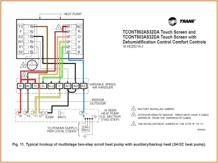
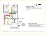
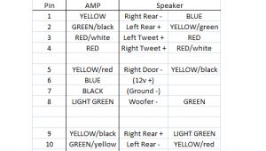
hvac sensor wiring wiring diagram expert
A set of wiring diagrams may be required by the electrical inspection authority to embrace relationship of the house to the public electrical supply system.
Wiring diagrams will then count up panel schedules for circuit breaker panelboards, and riser diagrams for special facilities such as fire alarm or closed circuit television or supplementary special services.
You Might Also Like :
- 1998 toyota Sienna Radio Wiring Diagram
- 3 Wire Crank Sensor Wiring Diagram
- Car Stereo Installation Wiring Diagram
smart relay wiring diagram another image:
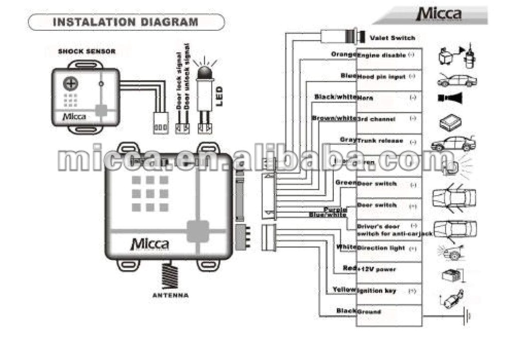
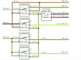
smart alarm wiring diagram wiring diagram mega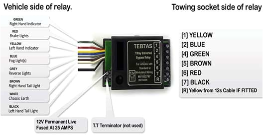
7 pin relay wiring diagram wiring diagrams schema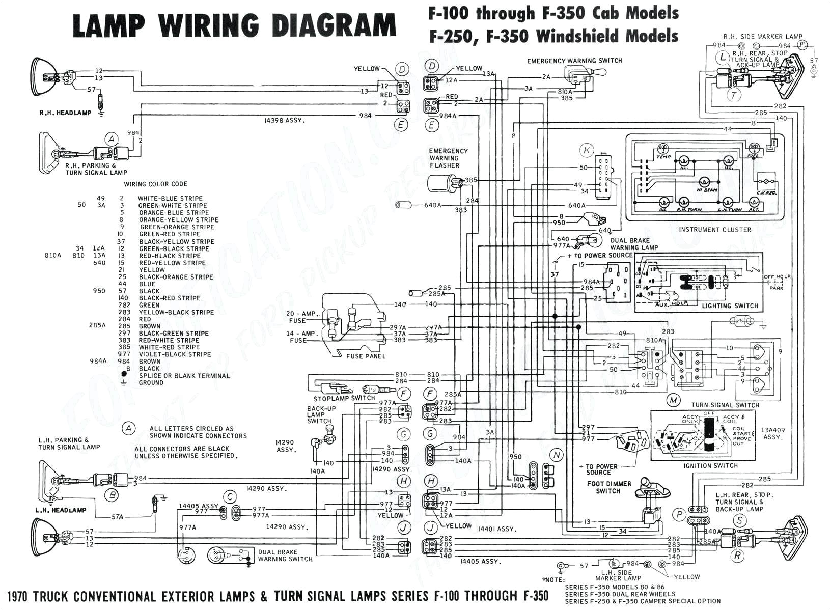
wiring diagram altec 6 04c wiring diagram rows
smart relay wiring diagram dogboi info idec smart relay programming manual smart relay idec smart relay moeller smart relays and how they function zelio smart relay programming here you are at our site contentabove smart relay wiring diagram published by admin 12v relay switch wiring diagram wiring diagram gallery 12v relay switch wiring diagram lovely 12v relay circuit diagram and 12v switch wiring wellread 12v relay switch wiring diagram amazon com online led store 6 pack 30a fuse relay switch harness 12v relay switch wiring diagram timer relay 10 minutes throughout 12v switch wiring diagram inside automotive relay guide 12 volt planet example relay wiring schemes the following diagrams show some common relay wiring schemes that use 4 pin iso mini relays 1 adding driving lights that come on with the headlight main beam this simple circuit uses the power feed to the headlight main beam bulb as the trigger to energise a relay the high current circuit in this relay feeds power to the driving light bulb so every time smart relay wiring diagram pores co so if you want to have the amazing photos related to smart relay wiring diagram just click save icon to store these photos to your laptop they are available for obtain if you like and wish to grab it simply click save logo on the page and it will be instantly downloaded in your laptop idec relay wiring diagram circuit diagram maker idec relay wiring diagram welcome thank you for visiting this simple website we are trying to improve this website the website is in the development stage support from you in any form really helps us we really appreciate that 8 channel 5v relay module for arduino raspberry pi this is a 5v 8 channel relay interface board be able to control various appliances and other equipment with large current it can be controlled directly by micro controller raspberry pi arduino 8051 avr pic dsp arm arm msp430 ttl logic idec smartrelay manual 2 2 wiring idec smartrelay 2 4 2 2 1 connecting the power supply 2 4 2 2 2 connecting idec smartrelay s inputs 2 6 2 2 3 connecting outputs 2 10 2 3 switching idec smartrelay on resumption of power supply 2 12 3 programming idec smartrelay 3 1 3 1 connectors 3 2 3 2 blocks and block numbers 3 4 3 3 from the circuit diagram to idec smartrelay 3 7 3 4 the 4 golden rules for working with idec wiring products how to wire an automotive relay instructions for wiring a standard automotive relay with descriptions of the pin out and the schematic please visit us at http www wiringproducts com 7 way universal bypass relay wiring diagram page 1 of 2 7 way universal bypass relay wiring diagram many modern cars have multiplexed or can bus wiring systems wiring systems such as can bus were starting system wiring diagram learn to navigate this system s wiring circuitry and diagram using current flow analysis relay and module operation and neutral switch actuation such as circuit completion see how the anti
