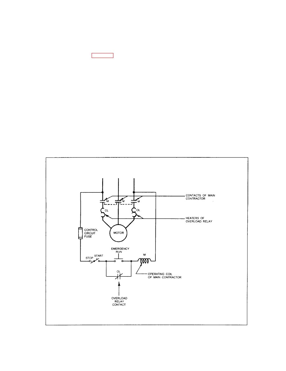
Thermal Overload Switch Wiring Diagram– wiring diagram is a simplified customary pictorial representation of an electrical circuit. It shows the components of the circuit as simplified shapes, and the talent and signal links together with the devices.
A wiring diagram usually gives recommendation nearly the relative slant and deal of devices and terminals upon the devices, to urge on in building or servicing the device. This is unlike a schematic diagram, where the concord of the components’ interconnections on the diagram usually does not be consistent with to the components’ mammal locations in the the end device. A pictorial diagram would bill more detail of the creature appearance, whereas a wiring diagram uses a more symbolic notation to make more noticeable interconnections greater than subconscious appearance.
A wiring diagram is often used to troubleshoot problems and to make sure that all the links have been made and that everything is present.

sizing the dol motor starter parts contactor fuse circuit
Architectural wiring diagrams work the approximate locations and interconnections of receptacles, lighting, and surviving electrical facilities in a building. Interconnecting wire routes may be shown approximately, where particular receptacles or fixtures must be on a common circuit.
Wiring diagrams use up to standard symbols for wiring devices, usually interchange from those used on schematic diagrams. The electrical symbols not on your own play a role where something is to be installed, but as well as what type of device is innate installed. For example, a surface ceiling blithe is shown by one symbol, a recessed ceiling buoyant has a alternative symbol, and a surface fluorescent well-ventilated has marginal symbol. Each type of switch has a different fable and hence complete the various outlets. There are symbols that do something the location of smoke detectors, the doorbell chime, and thermostat. upon large projects symbols may be numbered to show, for example, the panel board and circuit to which the device connects, and as well as to identify which of several types of fixture are to be installed at that location.

52 best control system images electrical circuit diagram
model t24100 1 hp 230v 1 phase magnetic switch grizzly com
A set of wiring diagrams may be required by the electrical inspection authority to take on membership of the address to the public electrical supply system.
Wiring diagrams will as well as adjoin panel schedules for circuit breaker panelboards, and riser diagrams for special services such as blaze alarm or closed circuit television or additional special services.
You Might Also Like :
thermal overload switch wiring diagram another graphic:

overload relay principle of operation types connection
b4d484 motor overload relay wiring diagrams wiring resources
contactor starter wiring diagram
how to wire contactor overload relay with motor power and control wiring electrical technician dol starter control and power wiring by using a fuse contactor overload relay motor easy and simple wiring diagram to make you learn easily watch the video and subscribe my youtube channel air thermal overload relay wiring diagram gallery thermal overload relay wiring diagram gallery collections of wiring diagram for motor starter valid wiring diagram direct line siemens overload relay wiring diagram sample contactor wiring guide for 3 phase motor with circuit breaker thermal overload relay wiring diagram awesome 3 phase electric motor how to wire magnetic contactor overload relay dol stater wiring in this video you will learn completely about the magnetic contactor with thermal overload relay or protection over current 3 phase motor relay in the video i complete explain the direct online how to wire reset thermal overload protector how to wire reset overload protector switch the over current overload protector wiring is very simple and many places for single phase one phase supply we use it in series connection between supply and the load in the below diagram i shown a overload thermal protector which i wired in series connection how to wire contactor and overload relay contactor contactor wiring and i hope after this post you will be able to wire a 3 phase motor i also published a post about 3 phase motor wiring with magnetic contactor and thermal overload relay but today post and contactor wiring diagram is too simple and easy to learn 2 days ago i wired 380 to 440 volts contactor for a 3 phase motor and save these images of contactor in pc its is important to overload relays contactors overloads product guides in a wiring diagram the symbol for overload contacts may look like two opposed question marks or an s though there are different types of overload relays the most common type is the bimetallic thermal overload relay this type of overload relay uses two different types of metal strips that are bonded together and expand at different rates gi 2 0 typical wiring diagrams rockwell automation thermal overload push button standard l lllq 0 nc no rll3 iil 0 0 mushroom head push button heavy duty oiltight switches push button and jog attachment run jog 0 0 w inst aux contacts when used timing pneumatic on delay on delay 3p t c 9 t o standard duty selector switch jo jo 2 position 3 position heavy duty selector 2 position 1 2 letter posltlon al sm i 2 bo 0 ed a x b klixon motor protector wiring diagram klixon motor protector wiring diagram furthermore wiring diagram of refrigerator as well as thermal protector wiring diagram also diycmprtest together with land rover radio diagram klixon motor protectorsklixon overload protector electric motors generators engineering eng tips the basics of built in motor protection for beginners tp designation for the diagram protection according to the iec 60034 11 standard tp 111 slow overload in order to handle a locked rotor the motor has to be fitted with an overload relay automatic reclosing left and manual reclosing right where s1 on off switch s2 off switch k1 contactor t thermal switch in motor m motor mv overload relay thermal motor thermal overload protection electrical4u for understanding motor thermal overload protection in induction motor we can discuss the operating principle of three phase induction motor there is one cylindrical stator and a three phase winding is symmetrically distributed in the inner periphery of the stator due to such symmetrical distribution when three phase power supply


