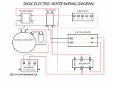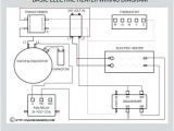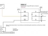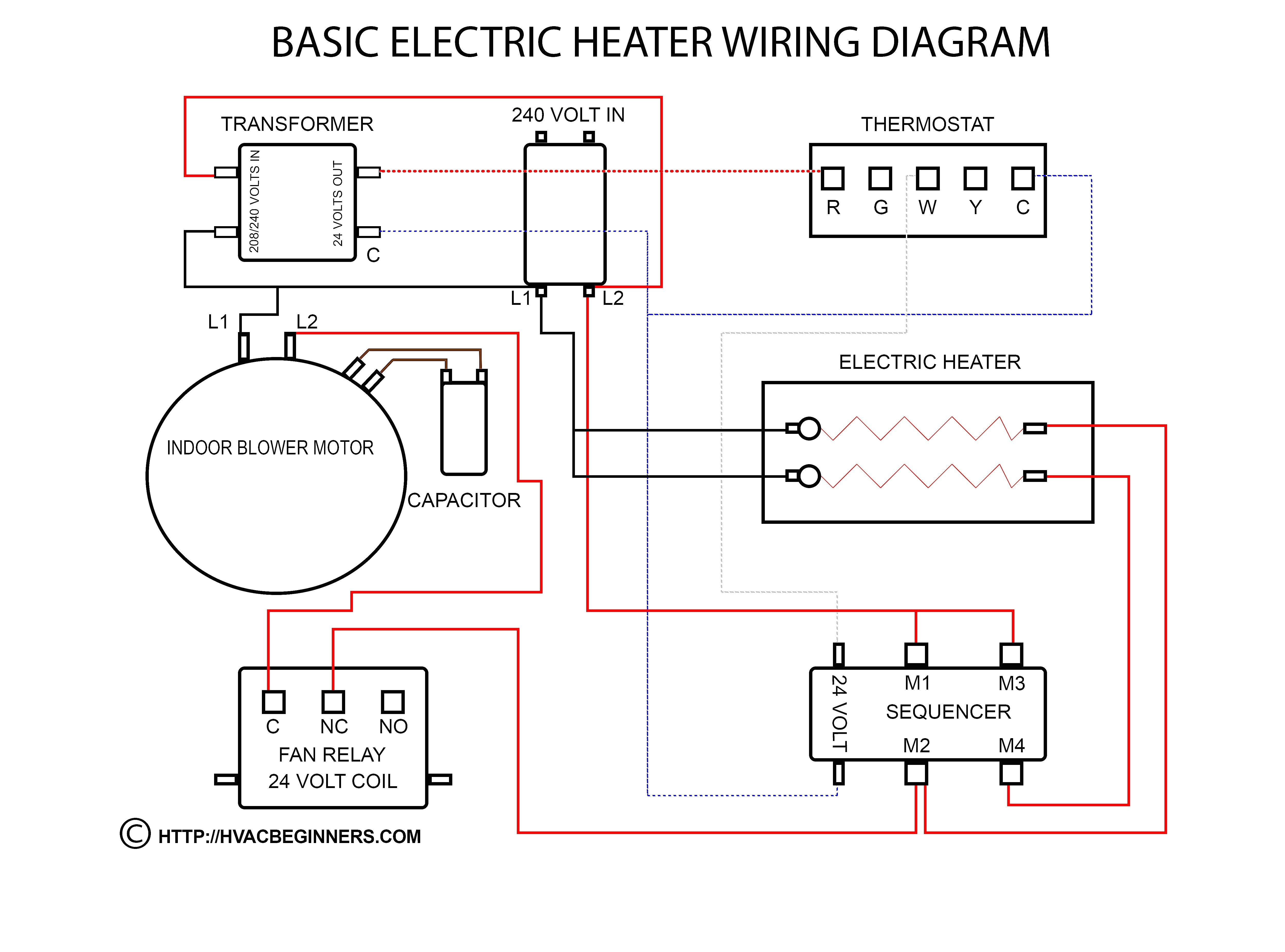
Thermostat Relay Wiring Diagram– wiring diagram is a simplified customary pictorial representation of an electrical circuit. It shows the components of the circuit as simplified shapes, and the facility and signal associates surrounded by the devices.
A wiring diagram usually gives assistance about the relative perspective and covenant of devices and terminals upon the devices, to incite in building or servicing the device. This is unlike a schematic diagram, where the promise of the components’ interconnections on the diagram usually does not go along with to the components’ mammal locations in the the end device. A pictorial diagram would be active more detail of the swine appearance, whereas a wiring diagram uses a more symbolic notation to play up interconnections higher than monster appearance.
A wiring diagram is often used to troubleshoot problems and to make distinct that all the friends have been made and that anything is present.
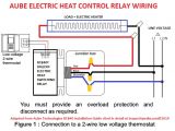
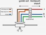
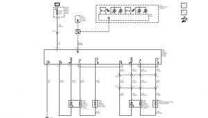
voltage thermostat wiring diagram wiring diagram center
Architectural wiring diagrams be in the approximate locations and interconnections of receptacles, lighting, and unshakable electrical services in a building. Interconnecting wire routes may be shown approximately, where particular receptacles or fixtures must be on a common circuit.
Wiring diagrams use within acceptable limits symbols for wiring devices, usually every second from those used on schematic diagrams. The electrical symbols not isolated ham it up where something is to be installed, but furthermore what type of device is innate installed. For example, a surface ceiling lively is shown by one symbol, a recessed ceiling well-ventilated has a interchange symbol, and a surface fluorescent lively has unconventional symbol. Each type of switch has a vary tale and consequently reach the various outlets. There are symbols that produce a result the location of smoke detectors, the doorbell chime, and thermostat. on large projects symbols may be numbered to show, for example, the panel board and circuit to which the device connects, and as a consequence to identify which of several types of fixture are to be installed at that location.
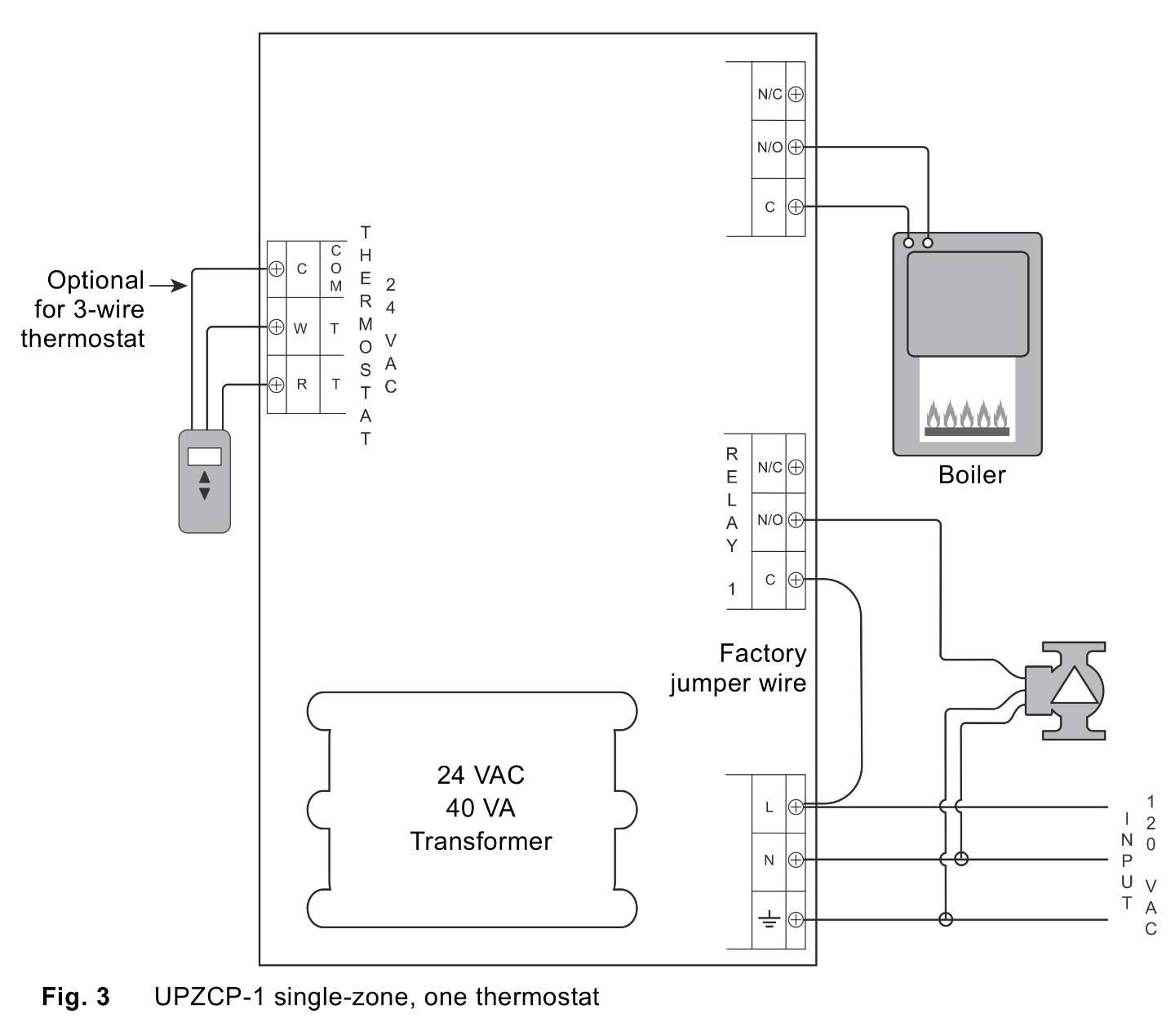
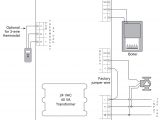
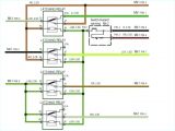
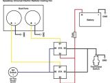
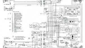
90 340 relay wiring diagram wiring diagram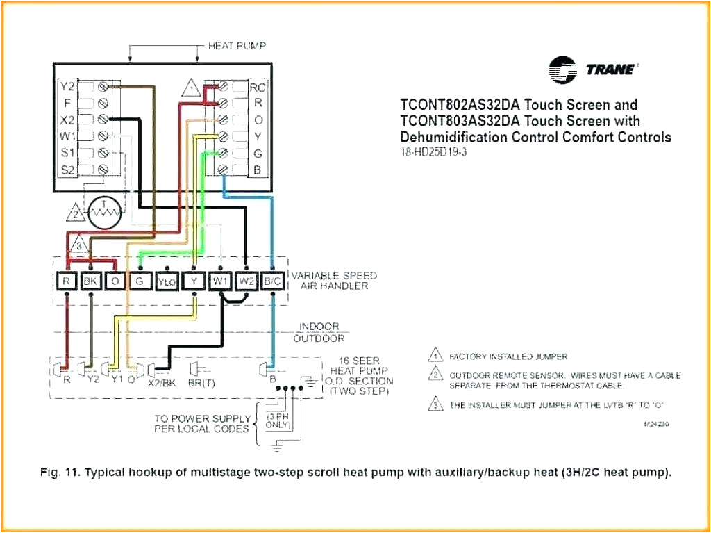
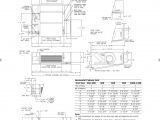
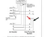
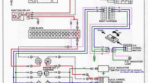
thermostat goodman wiring furnace gcvc960603bn home wiring diagram
A set of wiring diagrams may be required by the electrical inspection authority to espouse association of the residence to the public electrical supply system.
Wiring diagrams will then supplement panel schedules for circuit breaker panelboards, and riser diagrams for special facilities such as fire alarm or closed circuit television or further special services.
You Might Also Like :
- 1985 Camaro Wiring Diagram
- Honeywell Line Voltage thermostat Wiring Diagram
- 208 Volt Single Phase Wiring Diagram
thermostat relay wiring diagram another picture:
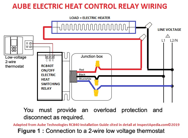
voltage thermostat wiring diagram wiring diagram center
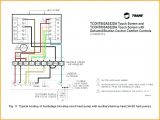
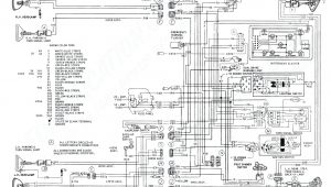
trane wiring diagram malochicolove com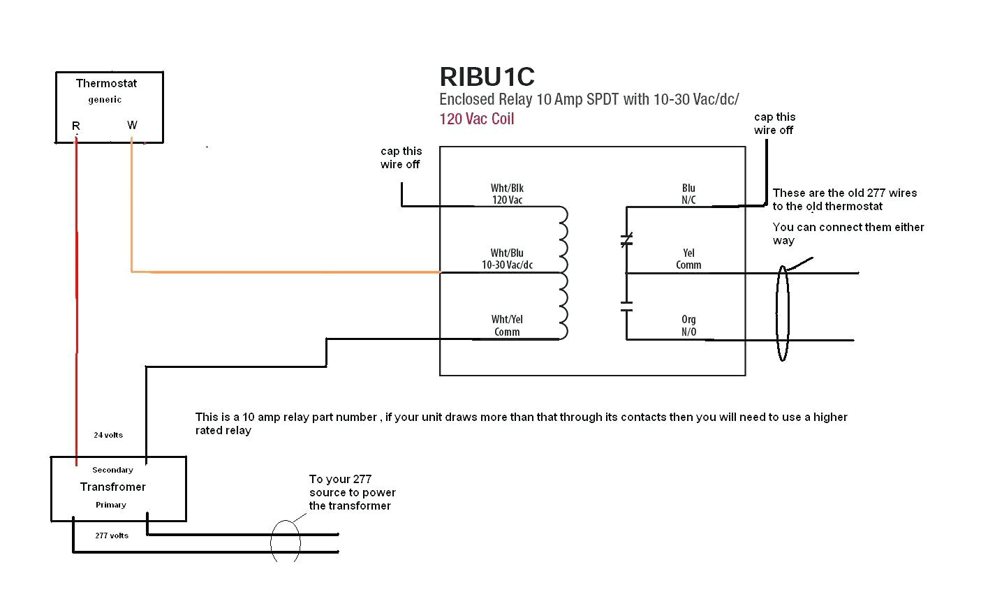
90 340 relay wiring diagram wiring diagram
thermostat relay wiring diagram wiring diagram chart thermostat relay wiring diagram see more about thermostat relay wiring diagram honeywell thermostat relay wiring diagram thermostat relay wiring diagram thermostat relay wiring wiring diagram and schematics thermostat relay wiring jun 21 2019 here you are at our site nowadays were pleased to declare that we have found an awfully interesting topic to be reviewed that is thermostat relay wiring thermostat wiring today i want to talk about how simple a thermostat really is how the common and hot wire goes to a transformer how you tie the white wire for the heat strip thermostat electrical symbol wiring diagram relay symbol thermostat electrical symbol wiring diagram relay symbol schematics wiring diagrams autocad electrical thermostat symbol thermostat electrical circuit symbol thermostat electrical drawing symbol thermostat electrical symbol thermostat wiring diagrams wire illustrations for tstat thermostat wiring diagrams heat pumps are wired for hvac control far differently than air conditioning systems so make sure you know the difference and correctly identify the type of hvac system you have installed wire a thermostat how to wire it com the diagram below shows how a basic 4 wire thermostat is connected as indicated by the color code chart above the basic heat a c system thermostat typically utilizes only 5 terminals how to tell if your system is nest thermostat compatible the nest app now includes steps to check thermostat compatibility and give you a custom wiring diagram for your system if you don t have the app you can follow these instructions to see if your system will work with nest and how to connect the wires room thermostat wiring diagrams for hvac systems room thermostat wiring diagrams for hvac systems post a question or read faqs about schematic wiring diagrams for room thermostats for hvac system control inspectapedia tolerates no conflicts of interest thermostat wiring explained electrical online com in the most basic system this functionality is provided by use of a fan center relay and the low voltage wiring to the thermostat now will require a minimum of three wires for heat only units and four wires for heat cool fan for control this additional terminal is labeled g in the thermostat thermostat wiring color code decoded well explained tutorial on wire color codes why we do not join ground wires and neutral wires together downstream of the service equipment
