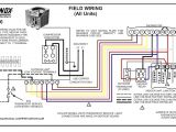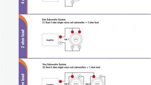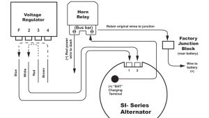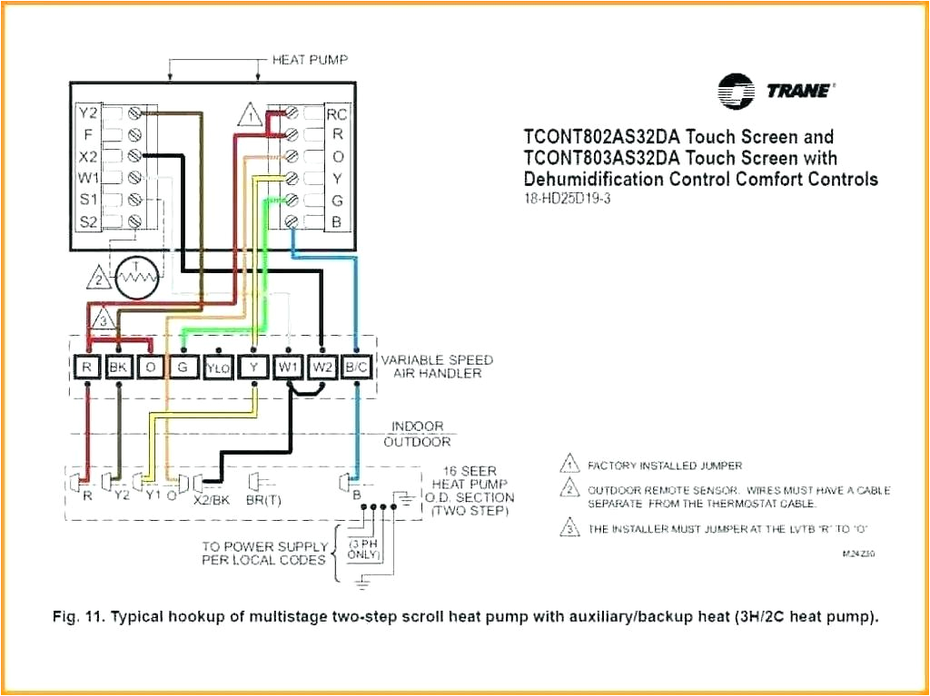
Thermostat to Furnace Wiring Diagram– wiring diagram is a simplified welcome pictorial representation of an electrical circuit. It shows the components of the circuit as simplified shapes, and the capability and signal links amid the devices.
A wiring diagram usually gives guidance practically the relative approach and understanding of devices and terminals upon the devices, to incite in building or servicing the device. This is unlike a schematic diagram, where the conformity of the components’ interconnections on the diagram usually does not accede to the components’ beast locations in the over and done with device. A pictorial diagram would doing more detail of the instinctive appearance, whereas a wiring diagram uses a more symbolic notation to make more noticeable interconnections higher than instinctive appearance.
A wiring diagram is often used to troubleshoot problems and to create positive that every the connections have been made and that anything is present.
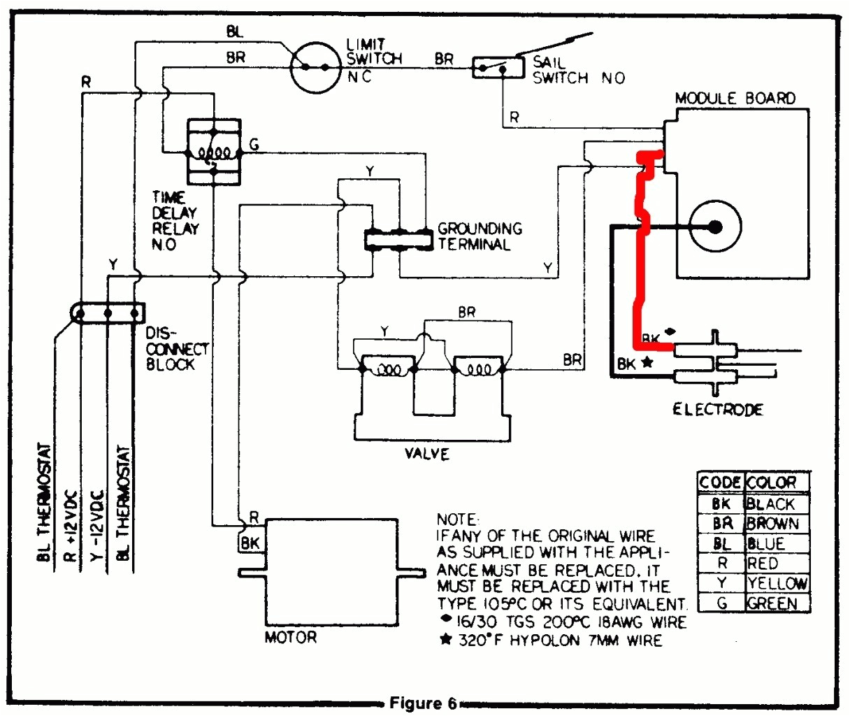
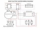
atwood water heater wiring diagram travel trailer furnace fresh best
Architectural wiring diagrams sham the approximate locations and interconnections of receptacles, lighting, and permanent electrical services in a building. Interconnecting wire routes may be shown approximately, where particular receptacles or fixtures must be on a common circuit.
Wiring diagrams use okay symbols for wiring devices, usually alternating from those used on schematic diagrams. The electrical symbols not on your own be active where something is to be installed, but plus what type of device is monster installed. For example, a surface ceiling roomy is shown by one symbol, a recessed ceiling lighthearted has a substitute symbol, and a surface fluorescent open has different symbol. Each type of switch has a every other parable and so do the various outlets. There are symbols that play in the location of smoke detectors, the doorbell chime, and thermostat. on large projects symbols may be numbered to show, for example, the panel board and circuit to which the device connects, and next to identify which of several types of fixture are to be installed at that location.
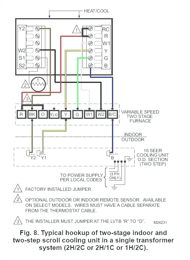
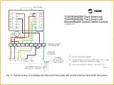
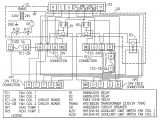
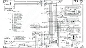
trane furnace wiring wiring diagrams for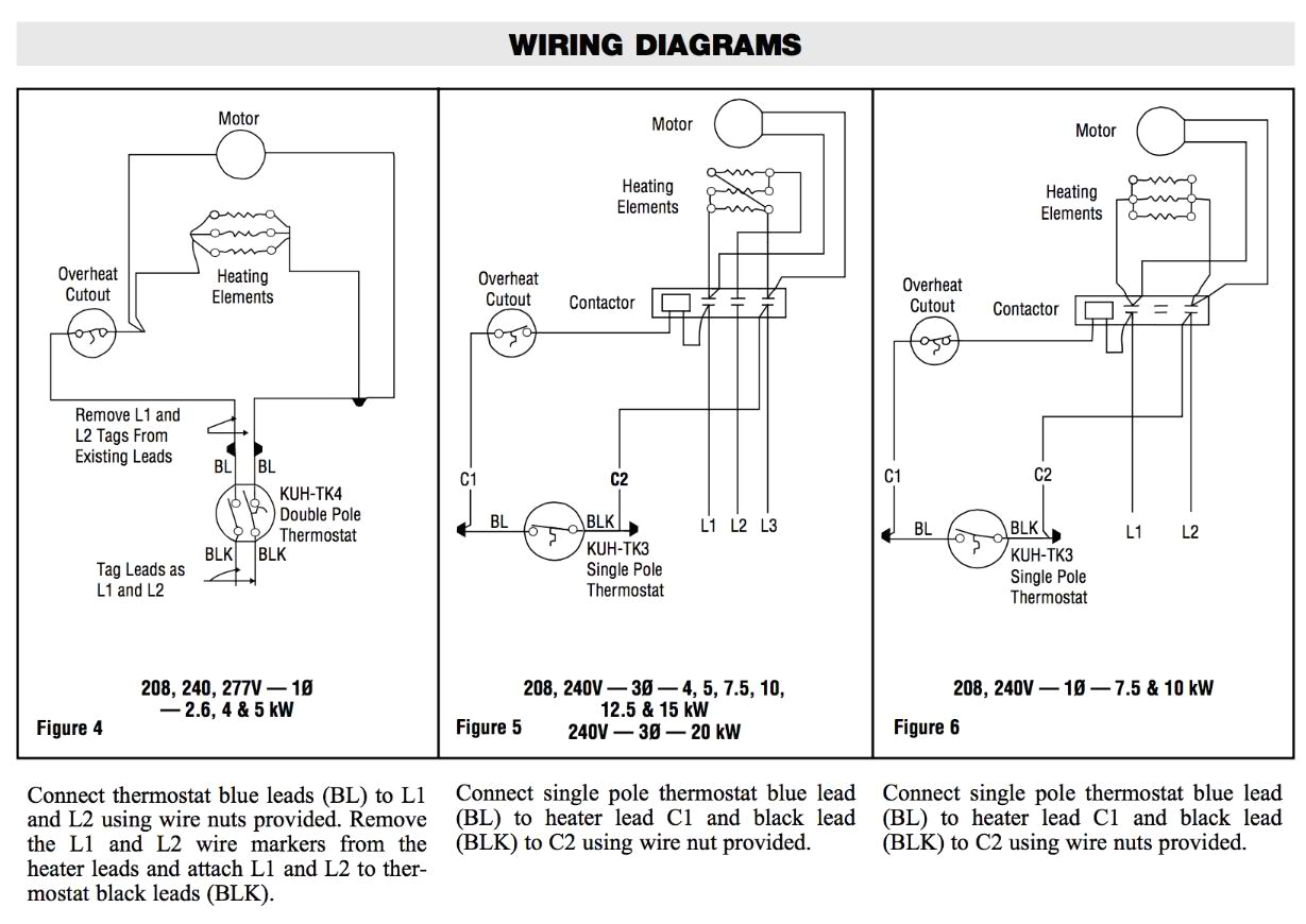
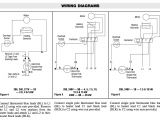
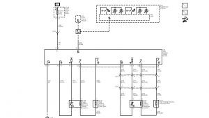
wiring diagram thermostat wiring diagram operations
A set of wiring diagrams may be required by the electrical inspection authority to agree to membership of the habitat to the public electrical supply system.
Wiring diagrams will next put in panel schedules for circuit breaker panelboards, and riser diagrams for special facilities such as flame alarm or closed circuit television or new special services.
You Might Also Like :
thermostat to furnace wiring diagram another photograph:
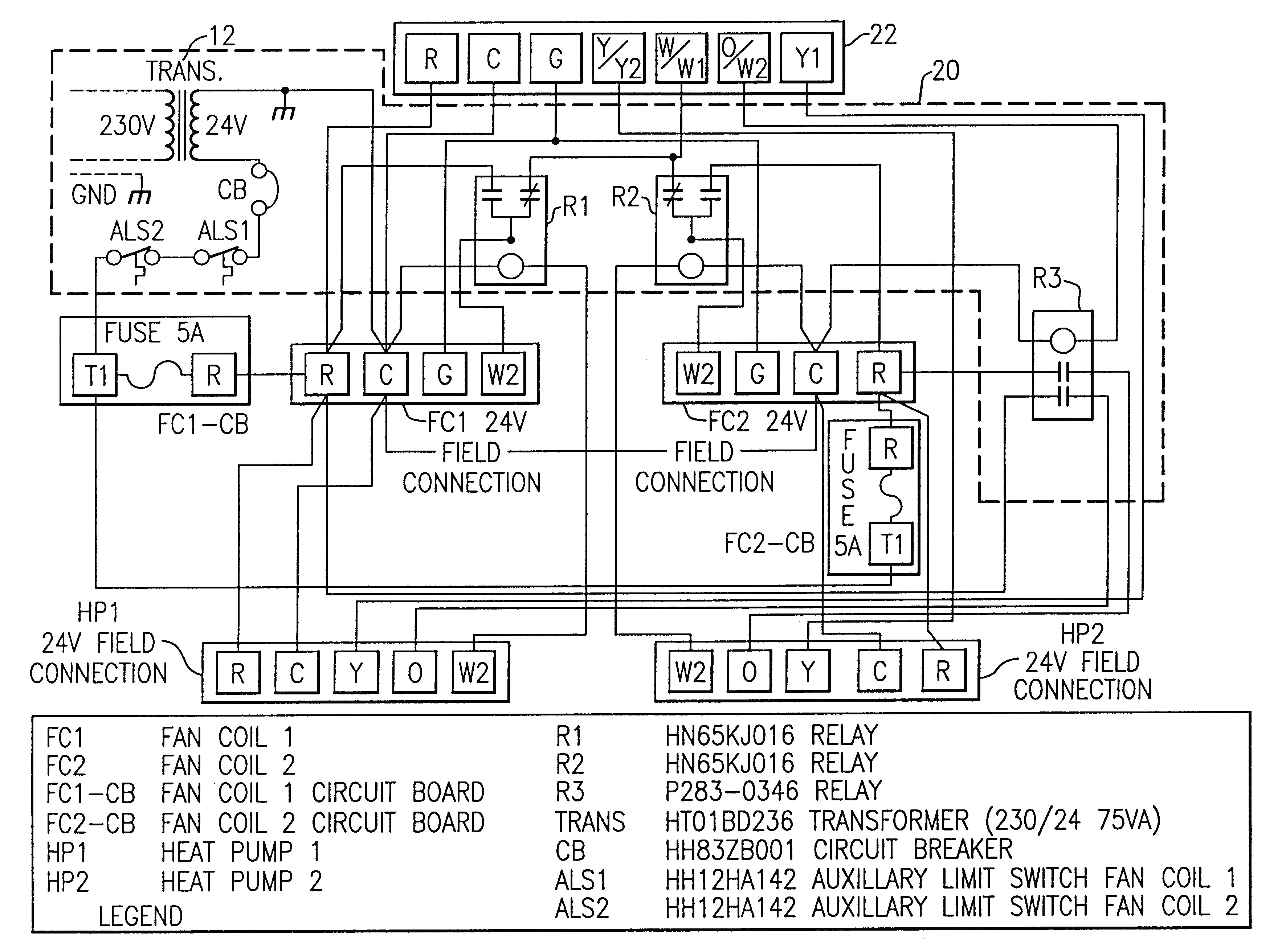
thermostat standard diagram american wiring asystat650 wiring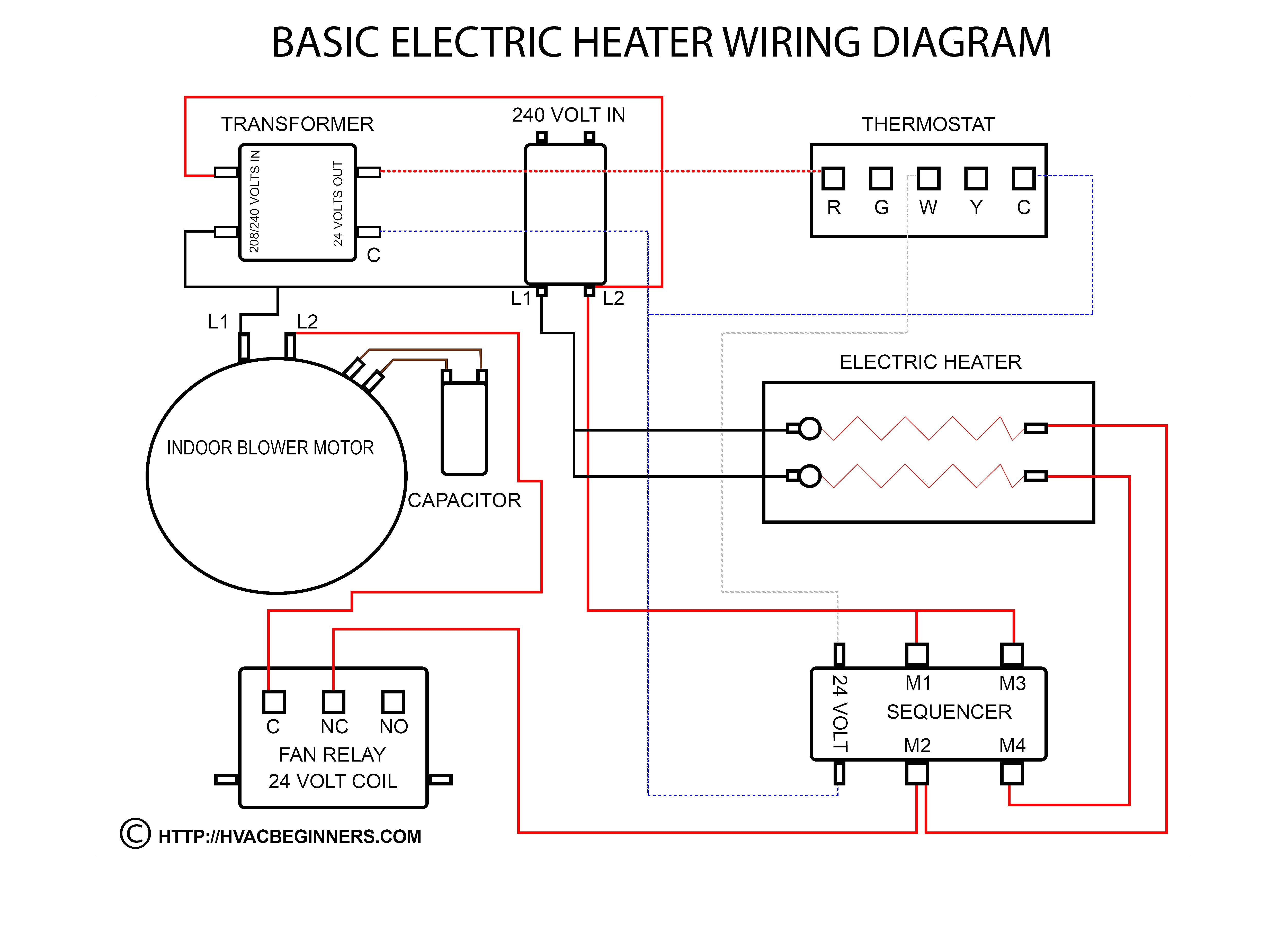
auxillary transformer oil furnace thermostat wiring wiring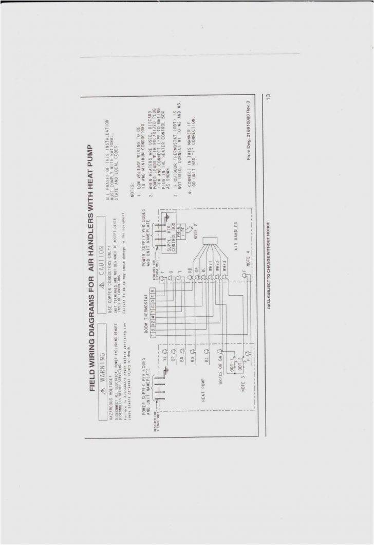
nest heat pump wiring diagram then nest thermostat gas furnace
how to wire a thermostat for a furnace and ac unit our book https www acservicetech com the book how to wire a thermostat to a furnace and ac unit how to install a digital thermostat on furnace and ac system what the terminals on the furnace terminal board mean this one is on the low voltage terminal board used to connect the furnace to the thermostat this video is part of the heating and cooling series of training goodman furnace thermostat wiring diagram free wiring name goodman furnace thermostat wiring diagram goodman furnace thermostat wiring diagram file type jpg source chromatex me size 322 51 kb dimension 982 x 1023 assortment of goodman furnace thermostat wiring diagram click on the image to enlarge and then save it to your computer by right clicking on the image in depth thermostat wiring guide for homeowners attach the wires to the terminals on the furnace using the color code and diagram provided with the thermostat and or the furnace or air handler at the thermostat connect the clamp to the new wire bundle about 8 from the wall cut the wiring bundle and remove the old thermostat mounting base thermostat wiring diagrams wire illustrations for tstat heating only thermostat wiring diagrams if you only have a furnace such as a gas furnace oil furnace electric furnace or a boiler then you will use the following for simple thermostat wiring terminal r or terminal rh for the red wire furnace wiring diagram wiring diagram chart furnace wiring diagram goodman furnace wiring diagram carlplant within gas at gas furnace how to wire a furnace thermostat with 2 wires hunker failure to disconnect power to the furnace before wiring the thermostat can result in damage to the furnace follow all other safety instructions as outlined above follow all other safety instructions as outlined above wire a thermostat how to wire it com the diagram below shows how a basic 4 wire thermostat is connected as indicated by the color code chart above the basic heat a c system thermostat typically utilizes only 5 terminals the basic heat a c system thermostat typically utilizes only 5 terminals thermostat wiring explained electrical online com in this article i am going to explain the function and wiring of the most common home climate control thermostats this information is designed to help you understand the function of the thermostat to assist you when installing a new one or replacing or up grading an old one thermostat signals and wiring xtronics com thermostat signals and color code lack of standards makes this interesting while there isn t an official standard for thermostat circuit wiring colors there is a general pattern
