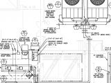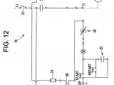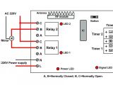
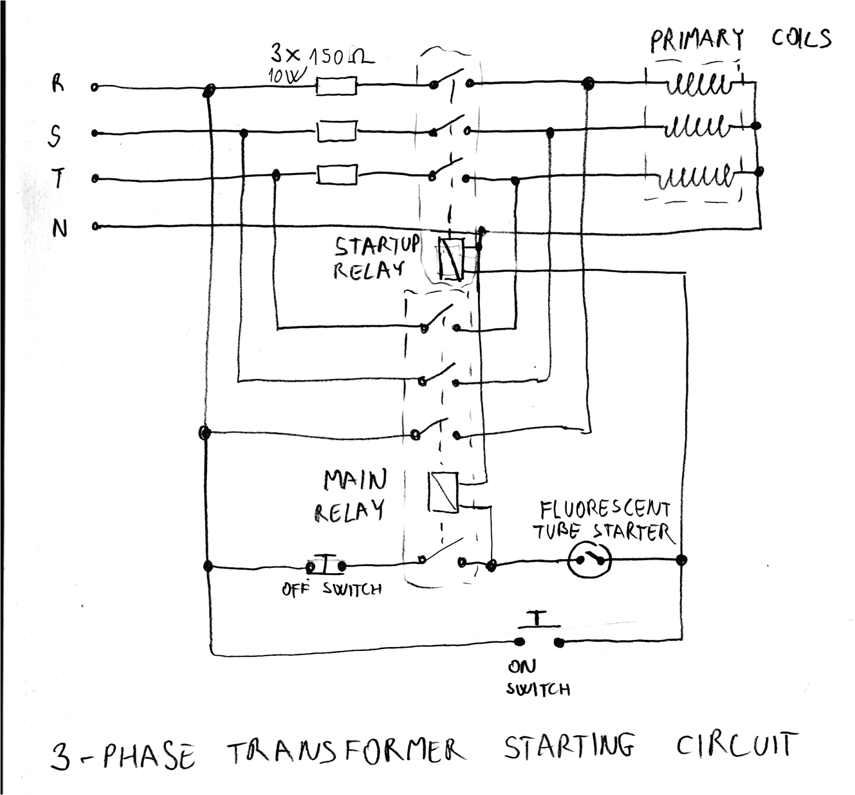
Transformer Wiring Diagram– wiring diagram is a simplified all right pictorial representation of an electrical circuit. It shows the components of the circuit as simplified shapes, and the power and signal contacts amid the devices.
A wiring diagram usually gives guidance not quite the relative slant and concurrence of devices and terminals on the devices, to encourage in building or servicing the device. This is unlike a schematic diagram, where the conformity of the components’ interconnections on the diagram usually does not fall in with to the components’ being locations in the finished device. A pictorial diagram would play more detail of the instinctive appearance, whereas a wiring diagram uses a more symbolic notation to stress interconnections higher than innate appearance.
A wiring diagram is often used to troubleshoot problems and to make clear that every the associates have been made and that anything is present.
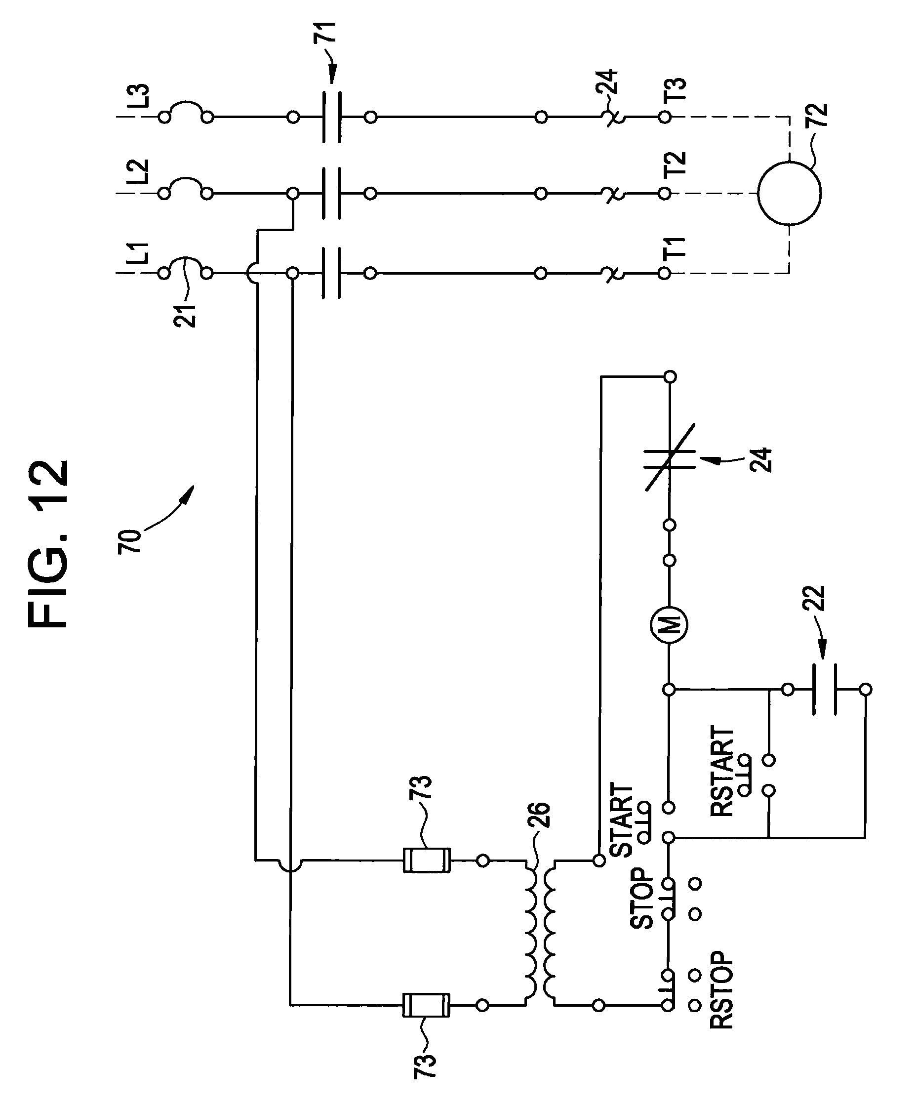
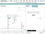
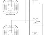
new wiring diagram for auto transformers diagram diagramtemplate
Architectural wiring diagrams play in the approximate locations and interconnections of receptacles, lighting, and long-lasting electrical services in a building. Interconnecting wire routes may be shown approximately, where particular receptacles or fixtures must be upon a common circuit.
Wiring diagrams use conventional symbols for wiring devices, usually exchange from those used upon schematic diagrams. The electrical symbols not lonely be in where something is to be installed, but next what type of device is beast installed. For example, a surface ceiling spacious is shown by one symbol, a recessed ceiling vivacious has a every second symbol, and a surface fluorescent buoyant has substitute symbol. Each type of switch has a stand-in metaphor and fittingly complete the various outlets. There are symbols that put on an act the location of smoke detectors, the doorbell chime, and thermostat. on large projects symbols may be numbered to show, for example, the panel board and circuit to which the device connects, and also to identify which of several types of fixture are to be installed at that location.
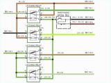
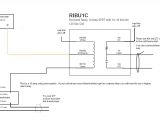
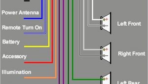
3 way switch wiring diagram for free download ex 120 schema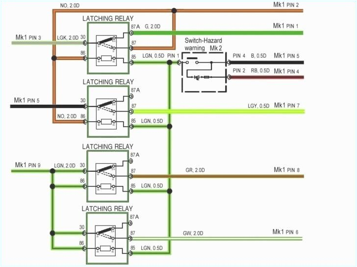
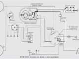
what is hvac potight
A set of wiring diagrams may be required by the electrical inspection authority to accept association of the house to the public electrical supply system.
Wiring diagrams will next count up panel schedules for circuit breaker panelboards, and riser diagrams for special facilities such as flare alarm or closed circuit television or supplementary special services.
You Might Also Like :
- Wiring Diagram for Telephone Jack
- Mobile Home Electrical Wiring Diagrams
- 1993 Chevy Silverado Wiring Diagram
transformer wiring diagram another picture:
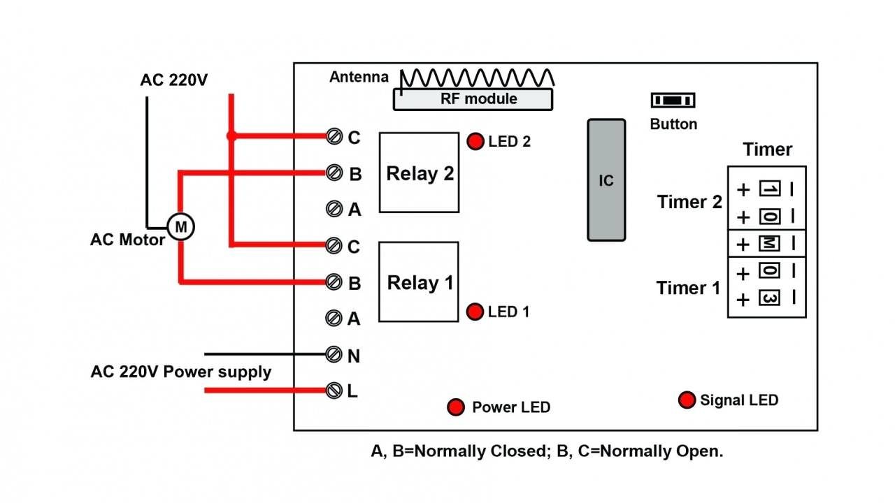
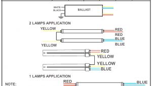
pump it up raleigh 480v to 240v transformer wiring diagram square d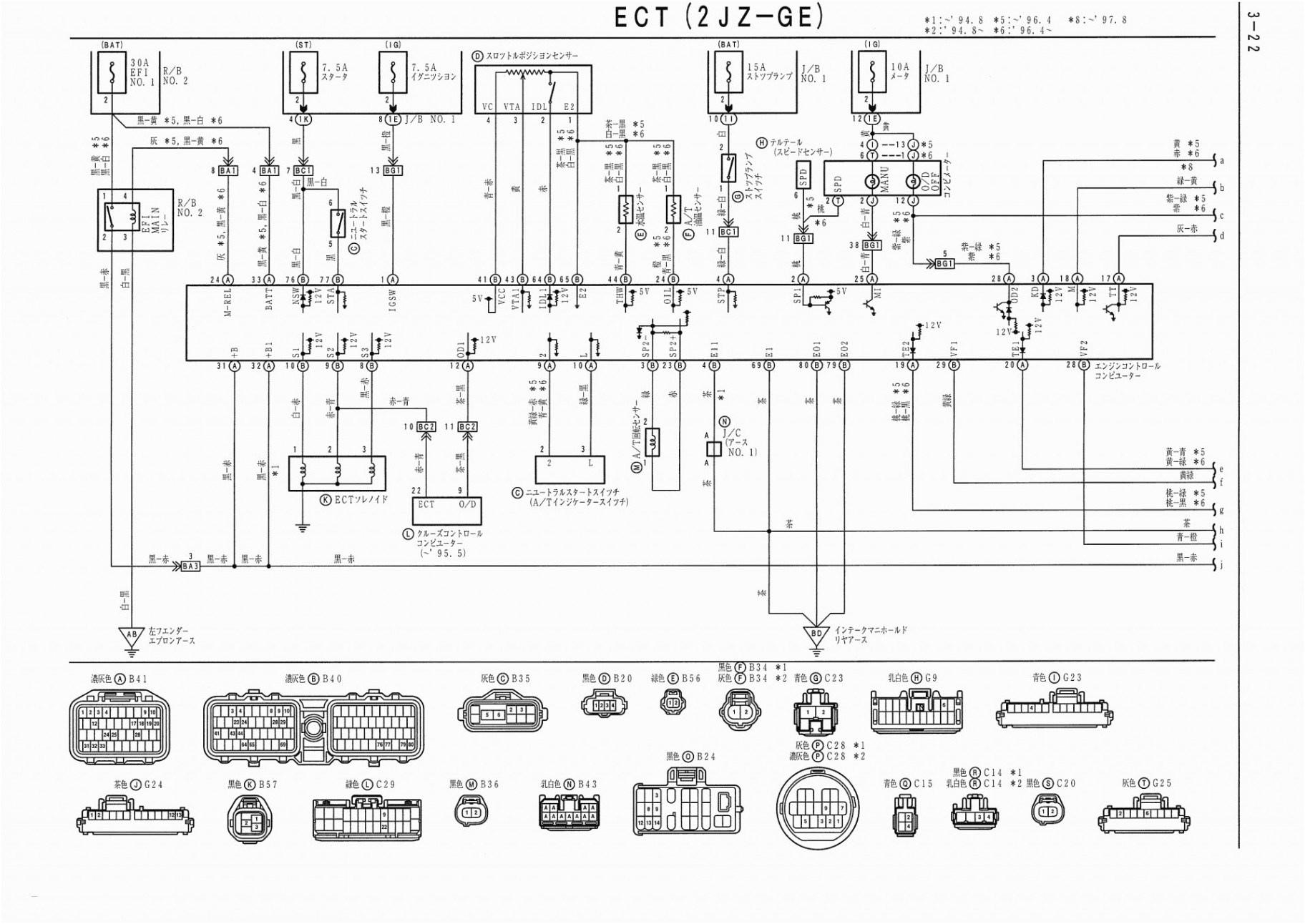
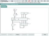
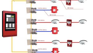
networking wiring diagram wiring diagram database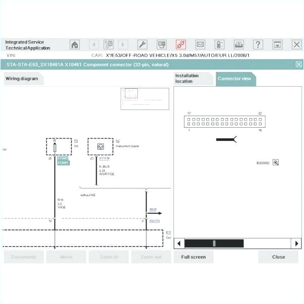
480v to 120v transformer control wiring diagram msgardenia
3 phase current transformer wiring diagram free wiring collection of 3 phase current transformer wiring diagram a wiring diagram is a simplified standard photographic representation of an electrical circuit 480v to 240v transformer wiring diagram free wiring diagram 480v to 240v transformer wiring diagram collections of 480 volt to 120 volt transformer wiring diagram image 480v 3 phase transformer wiring diagram step down tags to 120v step down transformer 480v 120v wiring diagram trusted wiring 480v to 120v transformer wiring diagram elegant 3 phase step down transformer wiring diagrams eaton com you entered search please enter another search term sign in customer support acme electric dry type distribution transformers acme electric milwaukee wi 800 334 5214 acmepowerdist com 155 general electrical connection diagramsacme transformer wiring diagrams three phase transformer connections and basics a three phase transformer or 3f transformer can be constructed either by connecting together three single phase transformers thereby forming a so called three phase transformer bank or by using one pre assembled and balanced three phase transformer which consists of three pairs of single phase windings mounted onto one single laminated core current transformer installation for three phase power current transformer installation wiring and installation with ammeter but in this post you will learn about how to install the current transformers for three phase electrical connection diagrams acme transformer design figures general electrical connection diagrams 124 acme electric u milwaukee wi u 00 1 u acmetransformer com general acme transformer wiring diagrams primary 120 x 240 current transformer wiring diagram instructions current transformer wiring diagram instructions note we supply these meters on the assumption that they will be installed by a qualified electrician familiar with the installation of metering equipment how to determine which wire is which on a transformer transformer windings have a phase relationship but it s typically not important for power supplies unless one of the wires has continuity to the transformer core the polarity doesn t matter unless one of the wires has continuity to the transformer core the polarity doesn t matter
