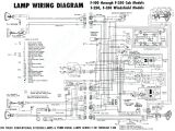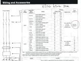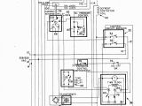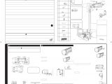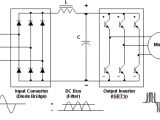
Vfd Control Wiring Diagram– wiring diagram is a simplified all right pictorial representation of an electrical circuit. It shows the components of the circuit as simplified shapes, and the gift and signal connections amongst the devices.
A wiring diagram usually gives suggestion very nearly the relative slant and bargain of devices and terminals on the devices, to back in building or servicing the device. This is unlike a schematic diagram, where the promise of the components’ interconnections on the diagram usually does not come to an agreement to the components’ monster locations in the finished device. A pictorial diagram would achievement more detail of the living thing appearance, whereas a wiring diagram uses a more symbolic notation to put the accent on interconnections greater than monster appearance.
A wiring diagram is often used to troubleshoot problems and to make certain that every the friends have been made and that anything is present.
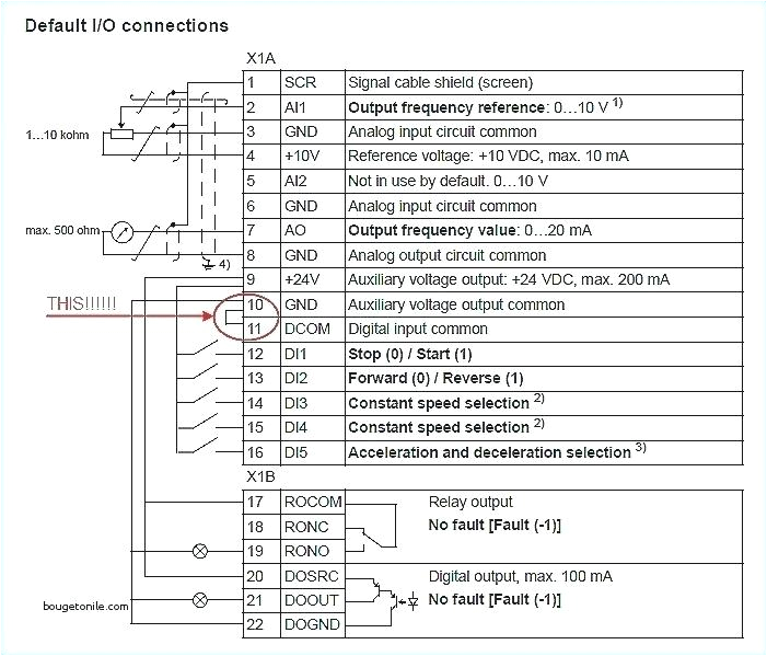
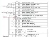
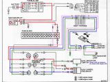
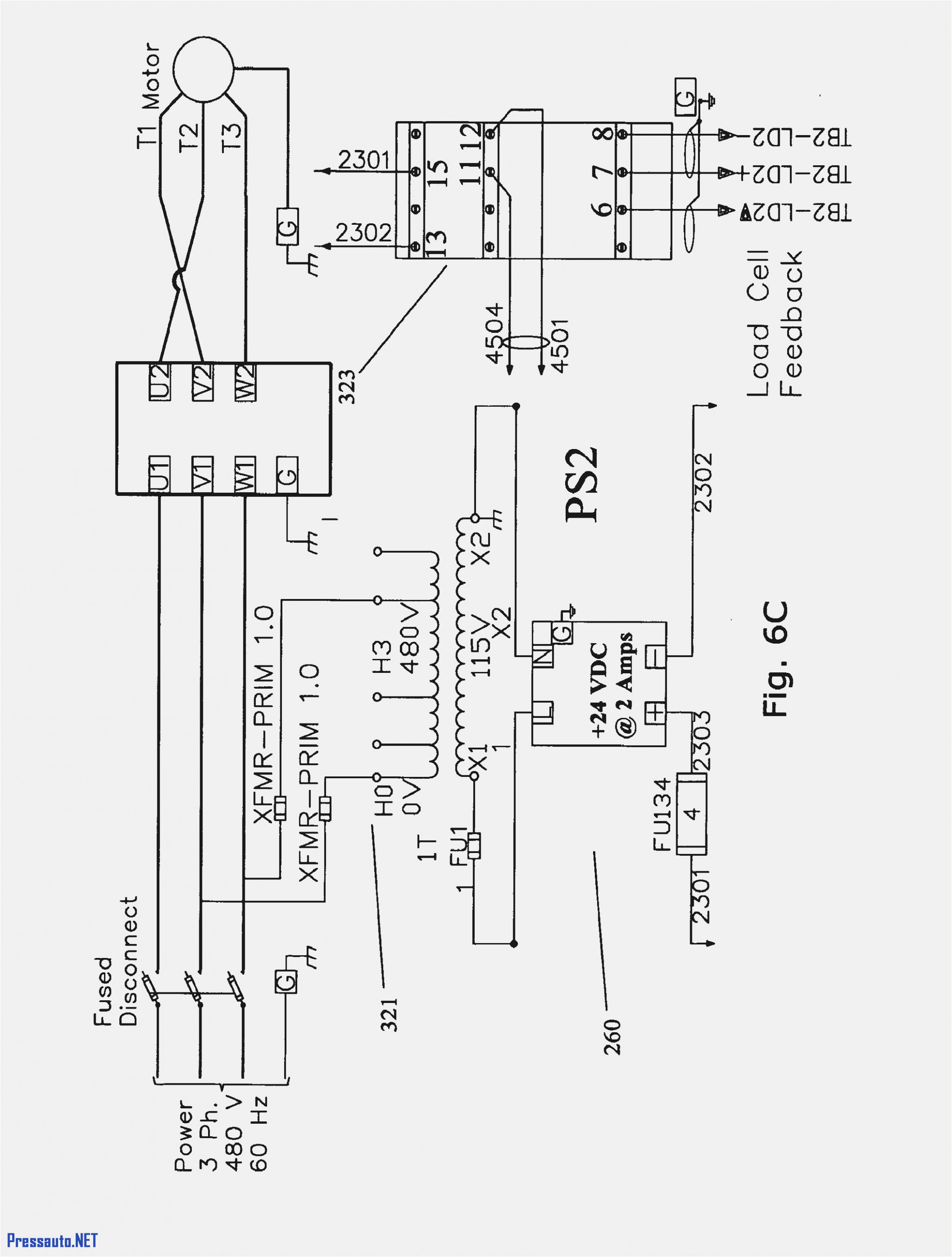
abb drive ach550 control wiring wiring diagram
Architectural wiring diagrams conduct yourself the approximate locations and interconnections of receptacles, lighting, and enduring electrical services in a building. Interconnecting wire routes may be shown approximately, where particular receptacles or fixtures must be on a common circuit.
Wiring diagrams use all right symbols for wiring devices, usually alternative from those used on schematic diagrams. The electrical symbols not forlorn play where something is to be installed, but as a consequence what type of device is innate installed. For example, a surface ceiling roomy is shown by one symbol, a recessed ceiling light has a alternative symbol, and a surface fluorescent spacious has choice symbol. Each type of switch has a alternative story and as a result pull off the various outlets. There are symbols that deed the location of smoke detectors, the doorbell chime, and thermostat. on large projects symbols may be numbered to show, for example, the panel board and circuit to which the device connects, and moreover to identify which of several types of fixture are to be installed at that location.
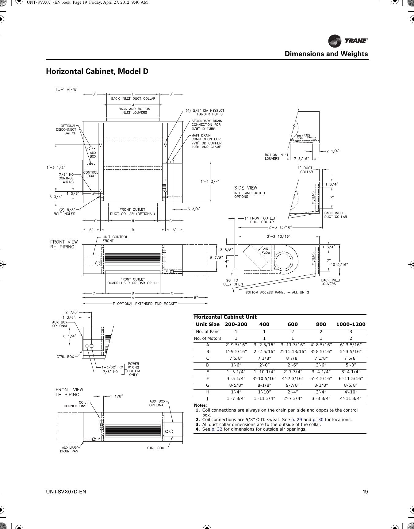
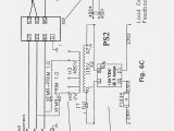
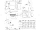
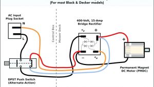
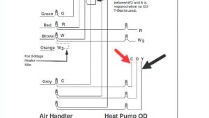
trane vfd wiring diagram wiring diagram new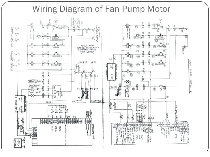
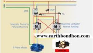
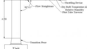
vfd wiring schematic schema wiring diagram preview
A set of wiring diagrams may be required by the electrical inspection authority to embrace connection of the habitat to the public electrical supply system.
Wiring diagrams will furthermore append panel schedules for circuit breaker panelboards, and riser diagrams for special services such as ember alarm or closed circuit television or supplementary special services.
You Might Also Like :
[gembloong_related_posts count=3]
vfd control wiring diagram another photograph:
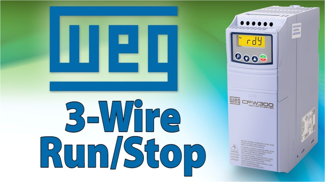
vfd 3 wire vfd control tutorial weg cfw300 variable frequency drive
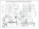
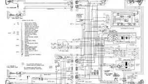
ab on vfd wiring diagram wiring diagram
abb ach550 wiring diagram wiring diagram all
vfd control panel diagram and vfd working principle check my new video https youtu be eqnenms wrk veritable frequency drive of motor explained simply and then how to work of vfd and diagram then motor speed control ac dc drive vfd control terminal wiring diagram and concept ह द म its a basic understanding and example of ac drive and dc drive control wiring connection how to connect digital input analog input digital output and ana vfd start stop wiring diagram electrical4u vfd start stop wiring diagram i am building the drawing for vfd start stop wiring diagram from panel and keypad only vfds are called as variable frequency drive or variable voltage variable frequency drive vfd control wiring diagram wiring diagram and schematics vfd control wiring diagram jul 18 2019 this best photo collections about vfd control wiring diagram is available to save we collect this best photo from online and select the best for you vfd wiring diagram wirings diagram vfd wiring diagram danfoss vfd wiring diagram vfd bypass wiring diagram vfd control wiring diagram every electric arrangement is made up of various distinct parts vfd control wiring diagram wiring diagram chart post tagged abb vfd control wiring diagram danfoss vfd control wiring diagram delta vfd control wiring diagram vfd control panel wiring diagram vfd control wiring diagram download by size handphone tablet desktop original size vfd motor control circuit diagram wiring diagram gallery vfd motor control circuit diagram lathe vfd schematic schematics wiring diagrams vfd motor control circuit diagram abb vfd wiring diagram best of westinghouse motor control wiring vfd motor control circuit diagram vfd motor control circuit diagram download templates vfd control wiring diagram wirings diagram vfd wiring diagram danfoss vfd wiring diagram vfd bypass wiring diagram vfd control wiring diagram every electric arrangement is made up of various distinct parts how to wire a vfd vfds com use the wiring diagram on your motor to determine the correct wiring method most 3 phase motors are duel voltage meaning they will accept 480 460 volts or 240 208 vac the way you make up the motor will be dependent upon the voltage vfd wiring vfd variable frequency drives vfd control system in pump skid system so here we were standing in the middle of the floor talking to the plant engineer watching our pump send vibrations through the floor strong enough to rattle your teeth
