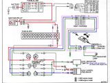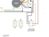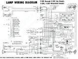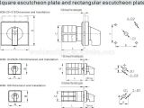
Voltage Selector Switch Wiring Diagram– wiring diagram is a simplified enjoyable pictorial representation of an electrical circuit. It shows the components of the circuit as simplified shapes, and the skill and signal associates surrounded by the devices.
A wiring diagram usually gives counsel about the relative position and conformity of devices and terminals on the devices, to put up to in building or servicing the device. This is unlike a schematic diagram, where the harmony of the components’ interconnections upon the diagram usually does not reach agreement to the components’ subconscious locations in the ended device. A pictorial diagram would put it on more detail of the beast appearance, whereas a wiring diagram uses a more symbolic notation to stress interconnections beyond visceral appearance.
A wiring diagram is often used to troubleshoot problems and to create certain that all the friends have been made and that whatever is present.
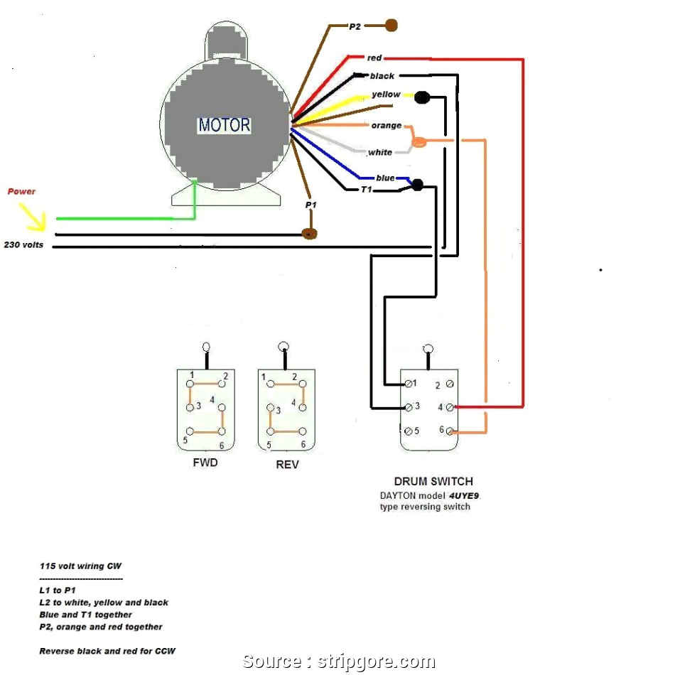
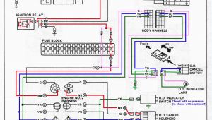
german motor wiring diagrams wiring diagram world
Architectural wiring diagrams accomplish the approximate locations and interconnections of receptacles, lighting, and enduring electrical facilities in a building. Interconnecting wire routes may be shown approximately, where particular receptacles or fixtures must be upon a common circuit.
Wiring diagrams use agreeable symbols for wiring devices, usually substitute from those used upon schematic diagrams. The electrical symbols not forlorn piece of legislation where something is to be installed, but in addition to what type of device is living thing installed. For example, a surface ceiling lively is shown by one symbol, a recessed ceiling open has a swap symbol, and a surface fluorescent well-ventilated has marginal symbol. Each type of switch has a substitute metaphor and so pull off the various outlets. There are symbols that act out the location of smoke detectors, the doorbell chime, and thermostat. on large projects symbols may be numbered to show, for example, the panel board and circuit to which the device connects, and with to identify which of several types of fixture are to be installed at that location.
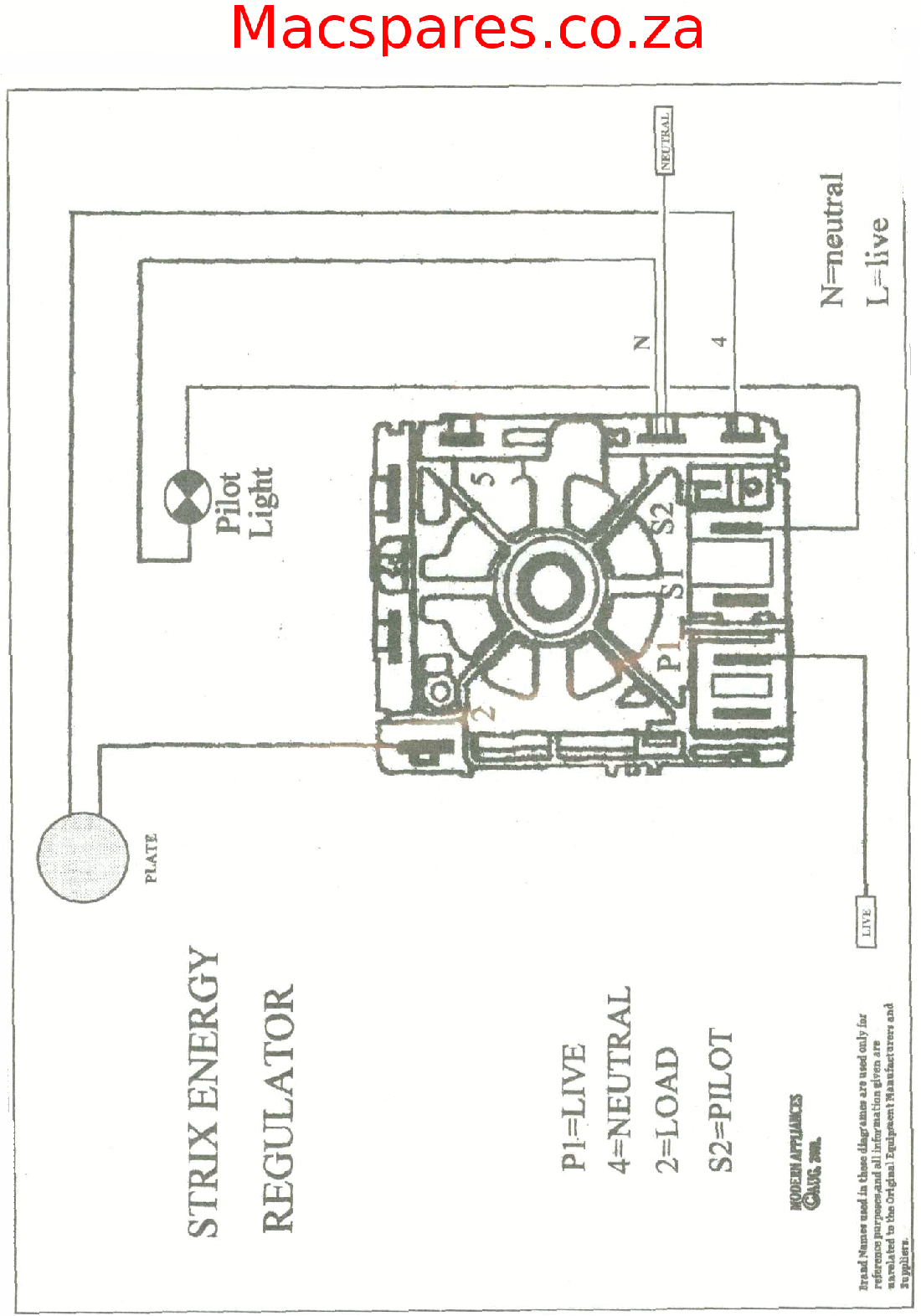
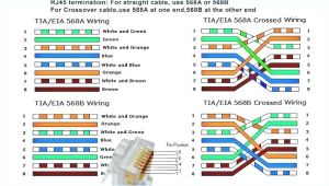
wiring diagrams stoves switches and thermostats macspares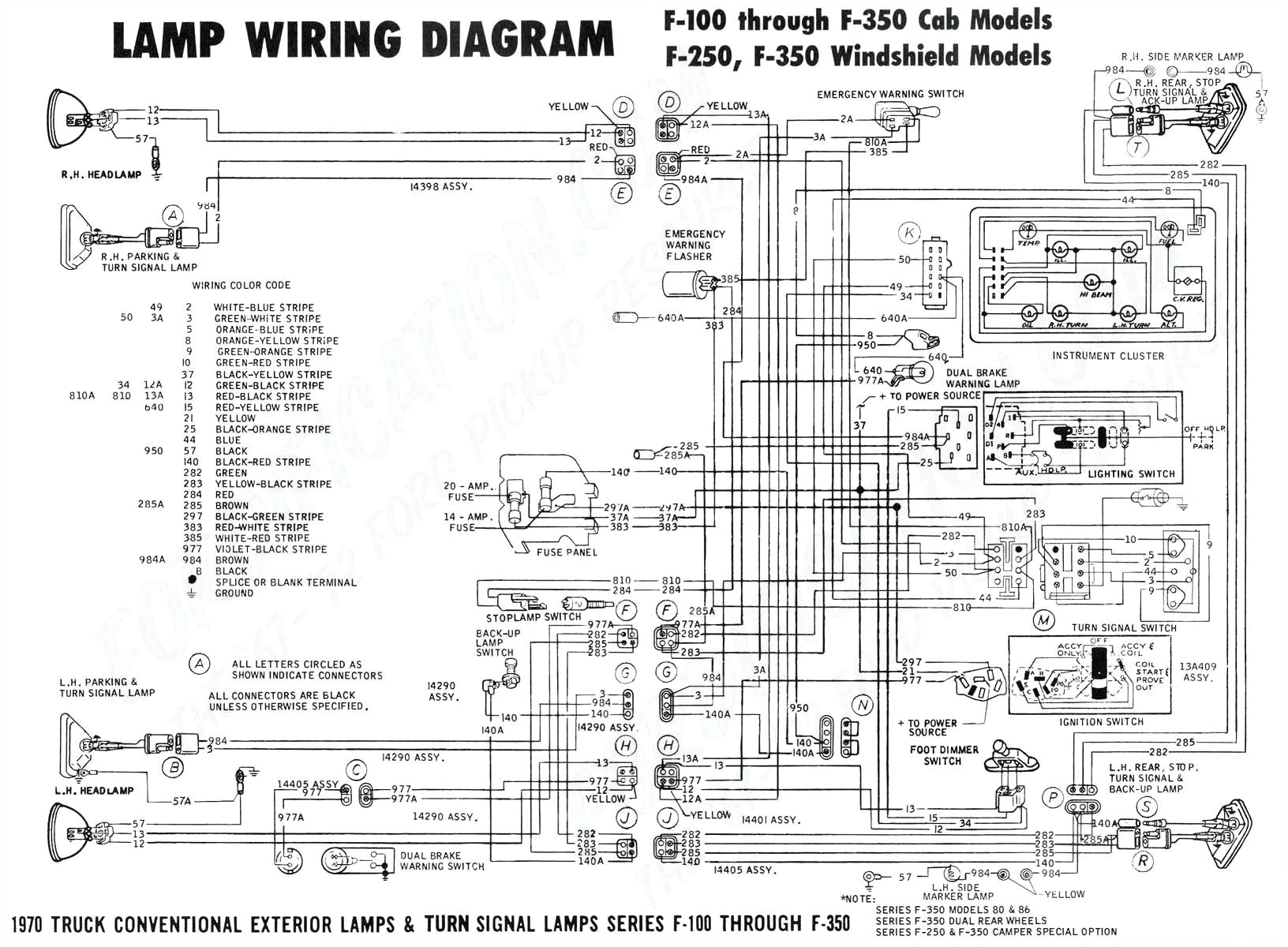
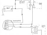
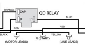
04 honda 250 ignition wiring wiring diagram used
A set of wiring diagrams may be required by the electrical inspection authority to take up link of the address to the public electrical supply system.
Wiring diagrams will with add up panel schedules for circuit breaker panelboards, and riser diagrams for special services such as flame alarm or closed circuit television or further special services.
You Might Also Like :
voltage selector switch wiring diagram another image:
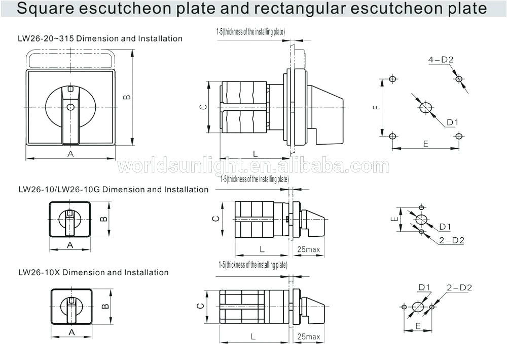
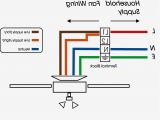
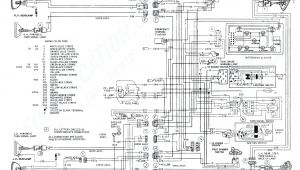
d1 wiring diagrams wiring diagram centre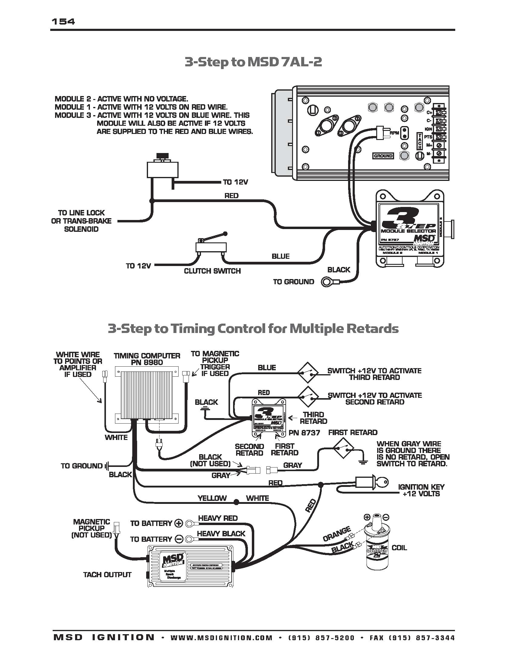
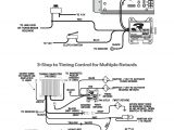
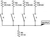
msd 3 step wiring diagram data diagram schematic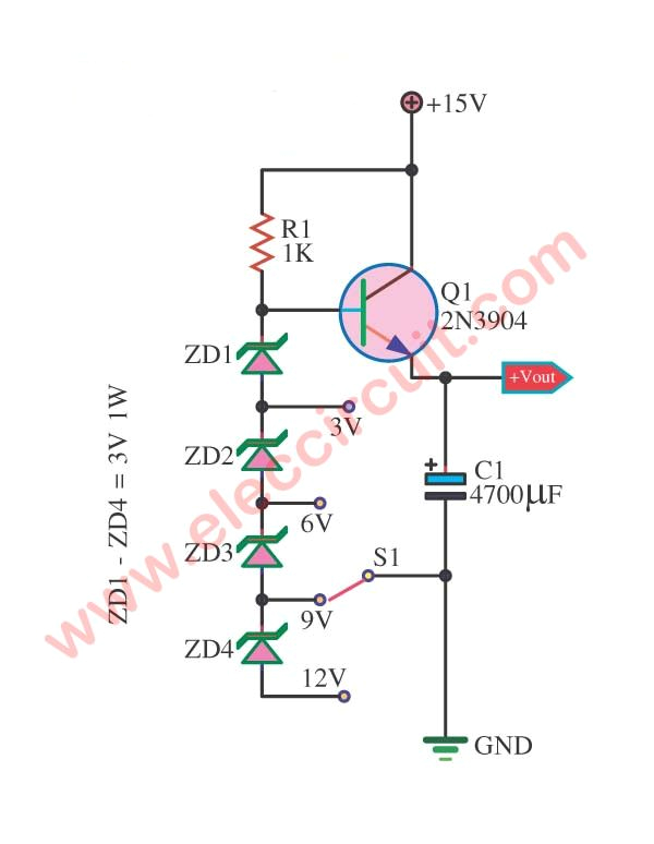
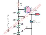
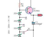
simple multi voltage step down converter circuit power supply
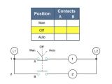
how to connect voltage selector switch and ammeter selector switch wiring diagram how to connect voltage selector switch and ammeter selector switch wiring diagram edison world loading unsubscribe from edison world cancel unsubscribe working subscribe subscribed voltmeter selector switch wiring diagram for three phase voltmeter selector switch wiring diagram for three phase as you know that if we instill the three voltage meter for 3 phase then it s will be a big lost of money how to connect selector switch how to connect voltmeter selector switch how to connect selector switch how to connect voltmeter selector switch voltage selector switch wiring diagram wiring diagram chart voltage selector switch wiring diagram see more about voltage selector switch wiring diagram 3 phase voltage selector switch wiring diagram voltage selector switch wiring diagram selector switch wiring diagram wiring diagram gallery selector switch wiring diagram see more about selector switch wiring diagram ammeter selector switch wiring diagram battery selector switch wiring diagram guitar generator voltage selector switch wiring diagram best generator voltage selector switch wiring diagram best place to find wiring and datasheet resources what is the right way to wire a power inlet to a switch to top position on the voltage selector is parallel wiring for the four outputs for 110 120v and bottom position is series wiring for 220 240v the four outputs on the inlet are numbered 2 4 3 1 from the top down in the diagram selector switches and contacts in a diagram what they do contact position on a selector switch can easily be illustrated using truth tables learn how this truth table illustrates the manual or automatic contact positions of two contact selector switch voltmeter selector switch wiring installation for 3 voltmeter selector switch wiring which was about the three phase voltage measuring and in which we did not talk about the neutral connection in this post i also write about voltmeter selector switch connection wiring but in the last time i talk and publish diagram about the 3 phase and in this post you will learn how to measure 3 phase 4 wire kraus naimer switch wiring diagrams pocketbook switch wiring diagrams the blue line 4 1 pole a20060 switching 1 32 2 pole a201 1 32 3 pole a202 2 32 4 pole a203 2 32 5 pole waa341 3 56 6 pole a342 3 56 7 pole a343 4 56 8 pole a344 4 56 9 pole waa345 5 56 10 pole a346 5 56 11 pole waa347 6 56 12 pole a348 6 56 1 pole a290 1 45 2 pole a291 1 45 3 pole a292 2 45 4 pole a324 2 54 4 pole a293 2 45 5 pole a325 3 54 6 pole a326 3 54 1 pole
