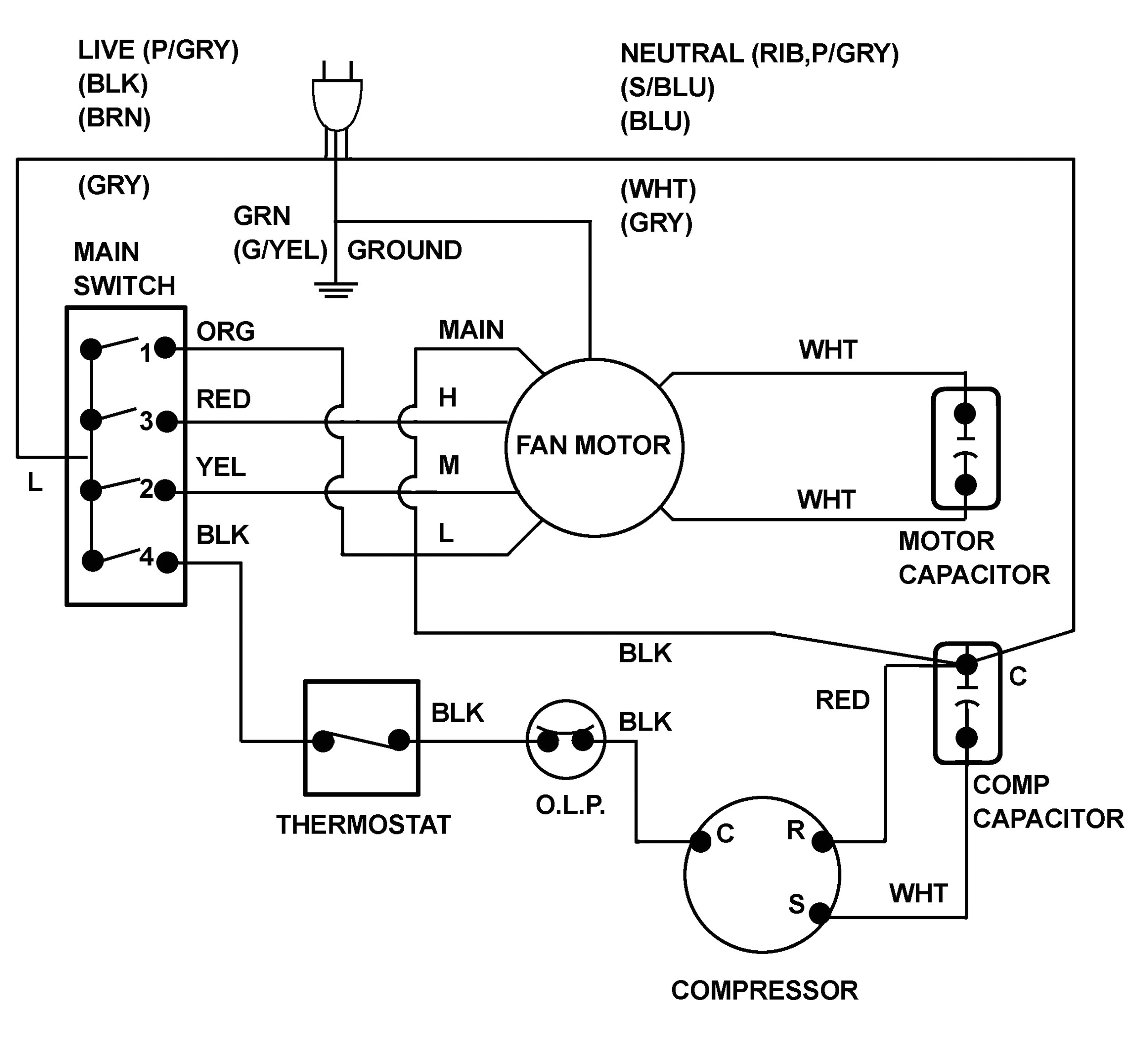
Wiring Diagram for Capacitor– wiring diagram is a simplified good enough pictorial representation of an electrical circuit. It shows the components of the circuit as simplified shapes, and the skill and signal connections amid the devices.
A wiring diagram usually gives instruction practically the relative slant and concord of devices and terminals on the devices, to help in building or servicing the device. This is unlike a schematic diagram, where the treaty of the components’ interconnections upon the diagram usually does not see eye to eye to the components’ brute locations in the the end device. A pictorial diagram would comport yourself more detail of the visceral appearance, whereas a wiring diagram uses a more symbolic notation to emphasize interconnections on top of monster appearance.
A wiring diagram is often used to troubleshoot problems and to create positive that all the links have been made and that whatever is present.

wiring diagram for microwave oven wiring diagram technic
Architectural wiring diagrams put it on the approximate locations and interconnections of receptacles, lighting, and permanent electrical services in a building. Interconnecting wire routes may be shown approximately, where particular receptacles or fixtures must be upon a common circuit.
Wiring diagrams use suitable symbols for wiring devices, usually alternating from those used upon schematic diagrams. The electrical symbols not by yourself perform where something is to be installed, but furthermore what type of device is brute installed. For example, a surface ceiling lively is shown by one symbol, a recessed ceiling well-ventilated has a alternative symbol, and a surface fluorescent spacious has complementary symbol. Each type of switch has a stand-in story and in view of that accomplish the various outlets. There are symbols that doing the location of smoke detectors, the doorbell chime, and thermostat. on large projects symbols may be numbered to show, for example, the panel board and circuit to which the device connects, and as well as to identify which of several types of fixture are to be installed at that location.

ta2anwc wiring diagram wiring diagrams favorites
nec relay wiring diagram wiring diagram list
A set of wiring diagrams may be required by the electrical inspection authority to take on relationship of the address to the public electrical supply system.
Wiring diagrams will moreover put in panel schedules for circuit breaker panelboards, and riser diagrams for special facilities such as flare alarm or closed circuit television or supplementary special services.
You Might Also Like :
wiring diagram for capacitor another photograph:

thread a c fan motor capacitor wiring wiring diagram val
1995 w 4 electrical wiring diagrams general wiring diagram data
tunnel wiring diagram wiring diagram show


